
Transport in plants (3.1.3)
On this page
Plants need a transport system to move:
- water and mineral ions from the roots to other parts of the plant
- assimilates (such as sucrose and amino acids) from sources to sinks
- hormones from where they are produced to their sites of action.
Transport systems are needed in plants because diffusion alone cannot meet the plant’s needs. Chemical reactions such as photosynthesis and respiration occur rapidly in plants – they have a high metabolic rate. Diffusion is too slow to meet these metabolic needs.
Plants are large organisms, which means they have a small surface area to volume ratio. As a result, diffusion across the surface would be too slow to supply all cells with the substances they need.
Plants are multicellular organisms, meaning that some cells are located far from the external surface. Transport is therefore required because the diffusion distance is too large and would be too slow to meet the plant’s metabolic demands.
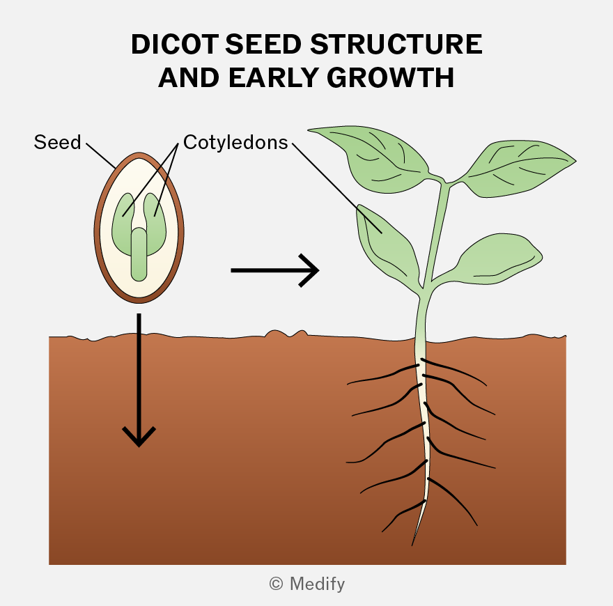
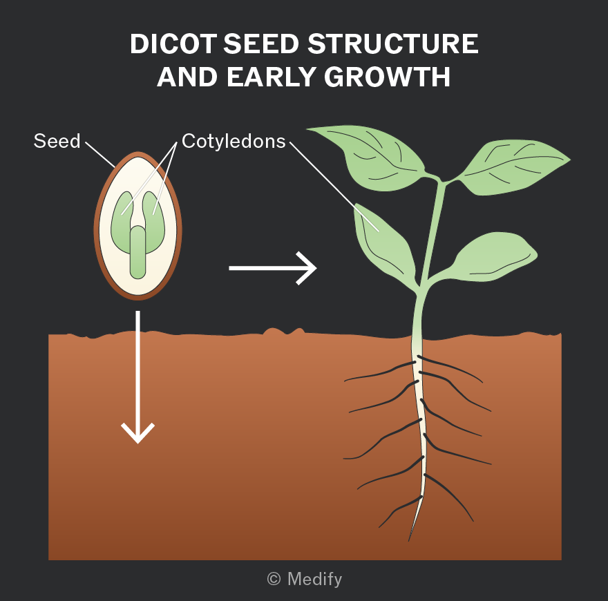
Dicotyledonous plants (dicots) produce seeds with two cotyledons (‘seed leaves’), which store food for the developing embryo and form the first leaves.
Dicots have a vascular system of xylem and phloem running through their stems, roots, and leaves. These transport tissues are arranged in vascular bundles.
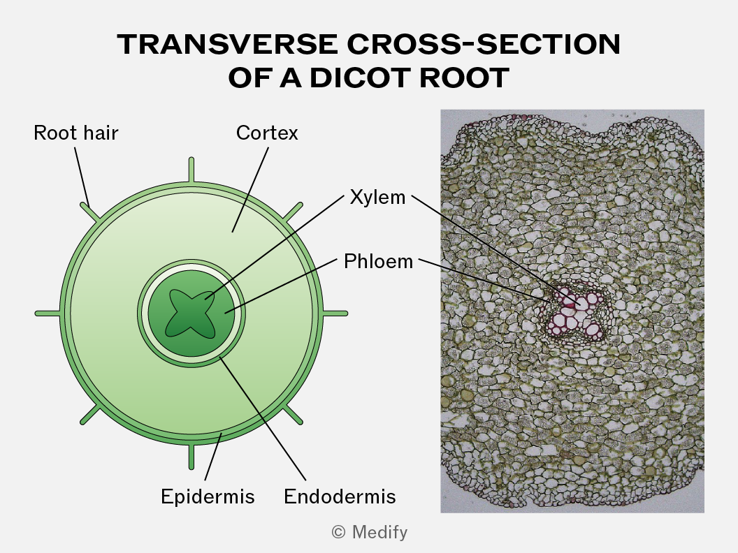
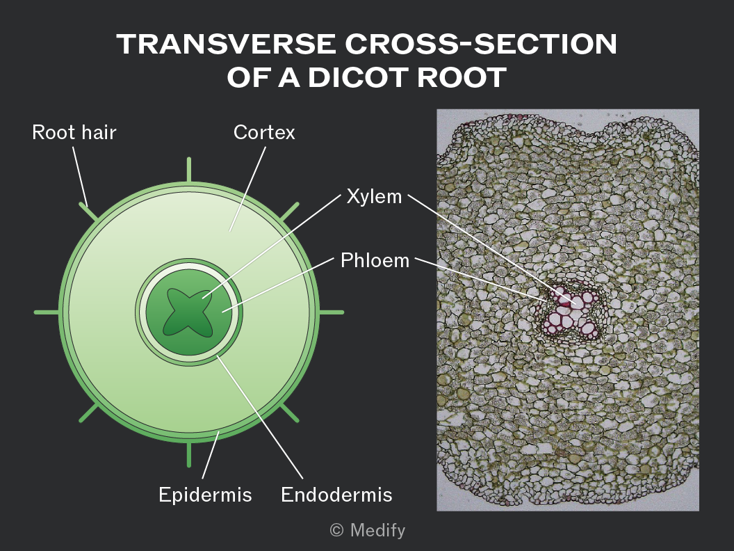
The xylem and phloem are located in the centre of the dicot root. In a transverse cross-section, xylem forms a cross or star-shaped pattern, while the phloem is situated between the arms of the xylem cross.
This arrangement provides structural support. It helps the root push through soil and gives the plant strength to withstand strains from stems and leaves blowing in the wind.
In dicot leaves, the xylem and phloem form a network of veins that provide both mechanical support and efficient transport within the leaf structure.
The xylem is usually located on the upper side of each vein, while the phloem is found on the lower side.
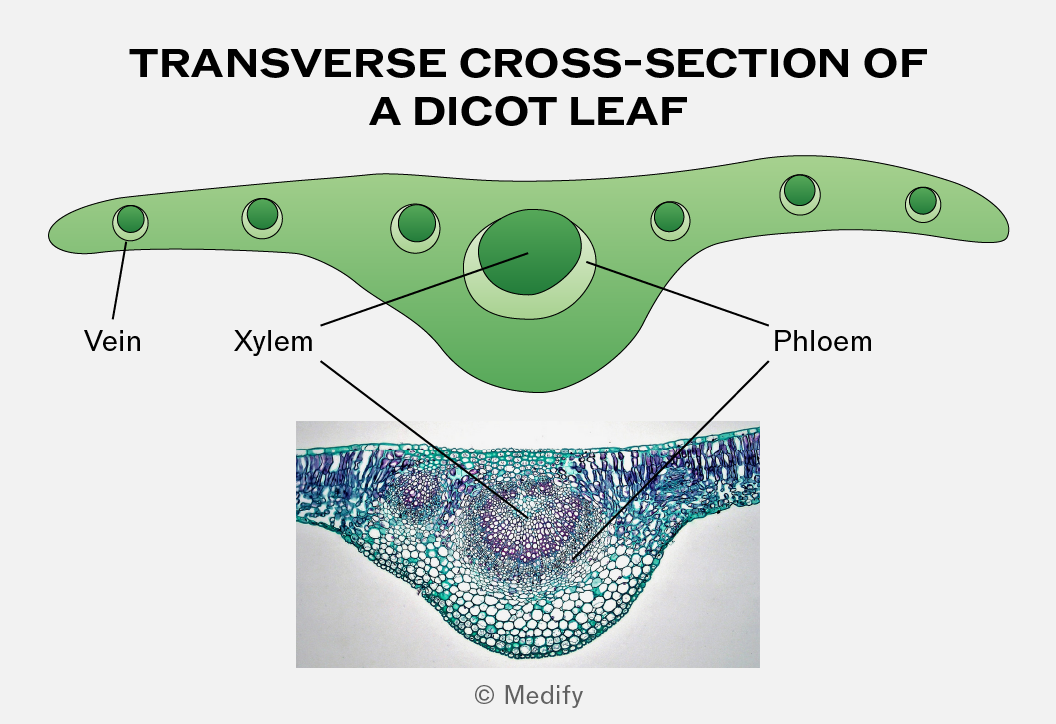
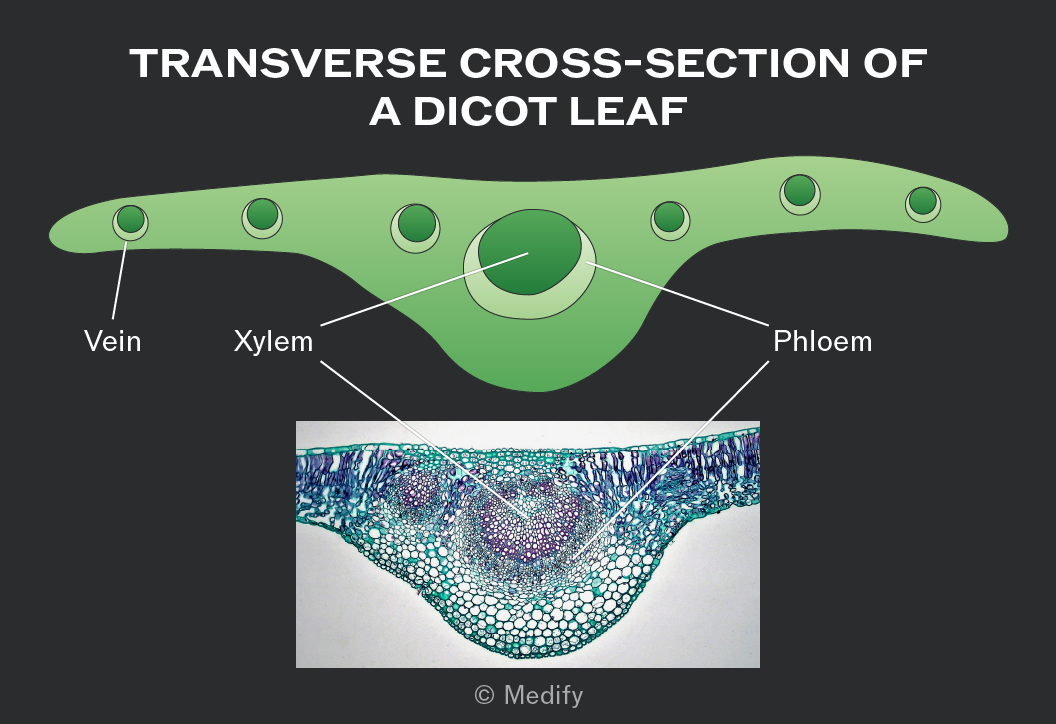
In a transverse cross-section of dicot stems, the vascular bundles are located near the outside of the stem in a ring arrangement.
The xylem is on the inner side of each vascular bundle, while the phloem is on the outer side.
This arrangement provides a scaffolding effect, reducing bending while still allowing some flexibility, so the stem does not snap.
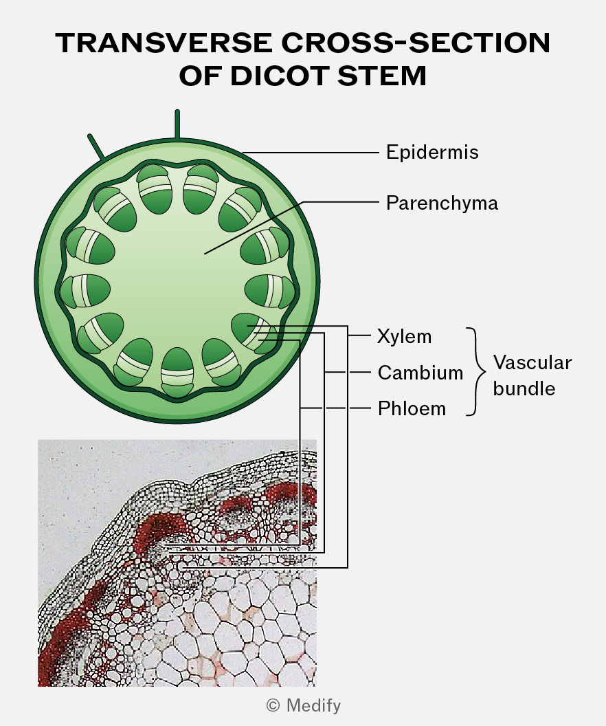
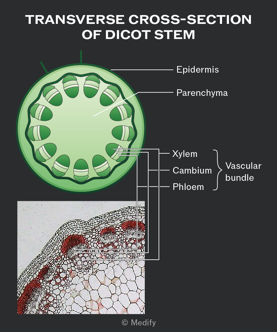
In a longitudinal section of a dicot stem, the xylem and phloem run as continuous strands along the length of the stem.
The xylem is on the inner side of each vascular bundle, while the phloem is on the outer side.
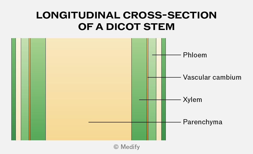
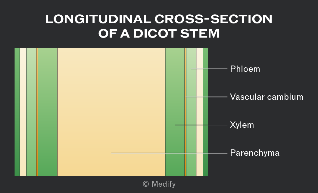
Under the microscope, xylem vessels can be identified as hollow, thick-walled, and lacking cytoplasm. They have a wider lumen than other vessels.
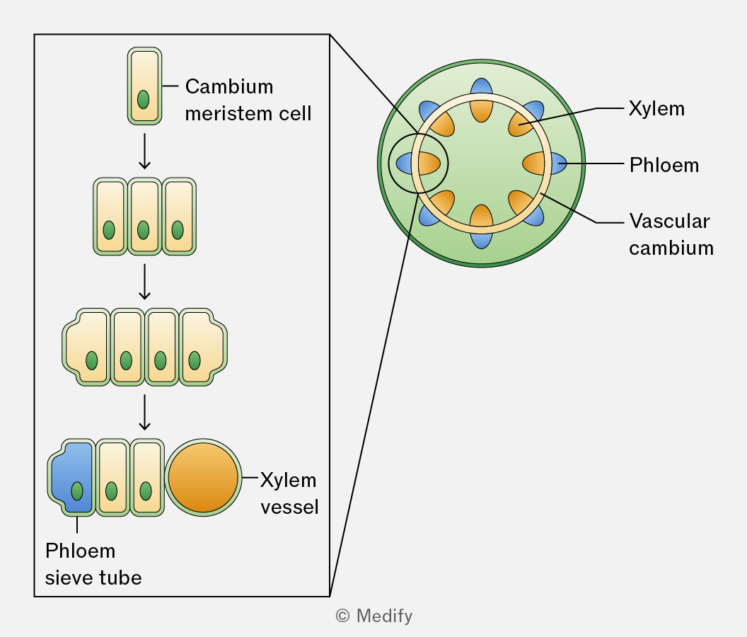
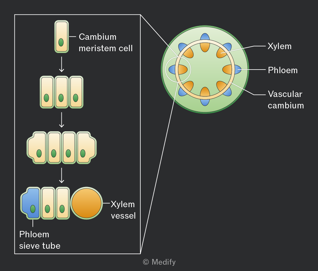
Meristematic tissue contains unspecialised stem cells that elongate and differentiate into xylem or phloem, allowing growth throughout the plant’s life.
This tissue can be found in the vascular cambium, located between xylem and phloem in the vascular bundles of stems.
To dissect and prepare a stem:
- Use a sharp scalpel to cut a thin transverse or longitudinal section.
- Place the sample on a microscope slide with a drop of water (wet mount).
- Use toluidine blue (TBO) to stain the xylem blue and phloem pink.
- Place a coverslip over the sample and gently squash it, allowing light to pass through for microscopy.
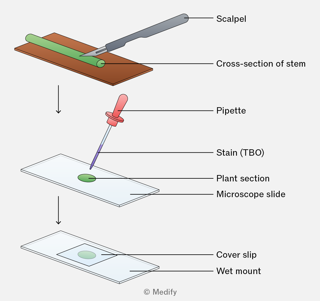
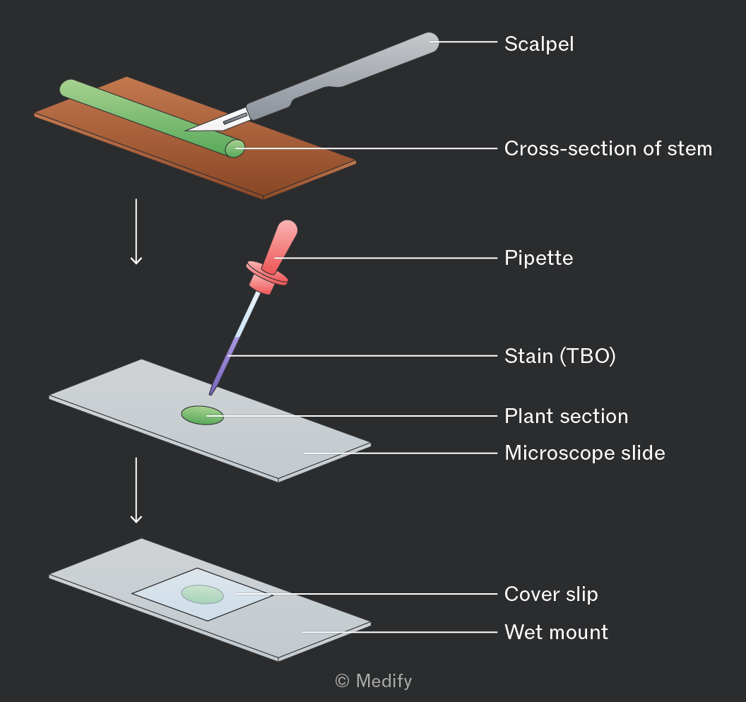
Several steps can be taken to reduce risk during the staining and dissection of a plant stem:
- Cut away from the body when dissecting a stem section with a sharp scalpel.
- Cut on a white tile or other solid surface.
- Use forceps to move the stained plant material to reduce contact with the skin and lower the risk of infection or allergic reactions.
Xylem vessels can also be seen in plants like celery by placing cut stems in coloured dye for 24 hours. The dye moves up the stem with the transpiration stream.
Transverse and longitudinal sections show dye-filled xylem, demonstrating the pathway of water from roots to leaves.
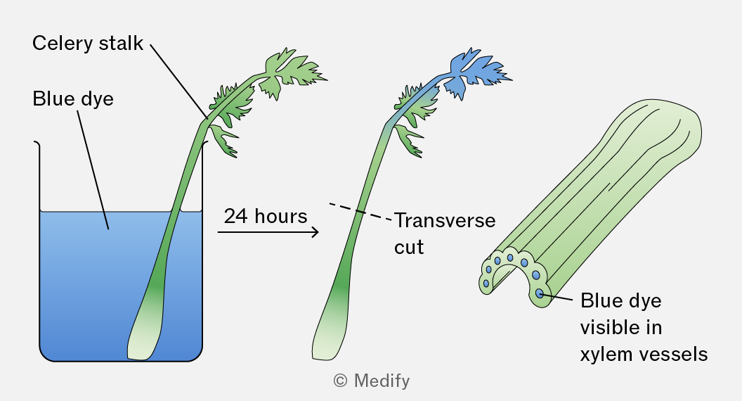
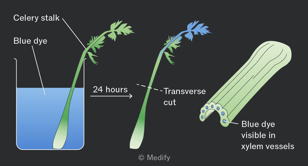
Xylem vessels:
- transport water and mineral ions from roots to leaves through the stem (one-way flow) via the transpiration stream
- provide mechanical support to the plant.
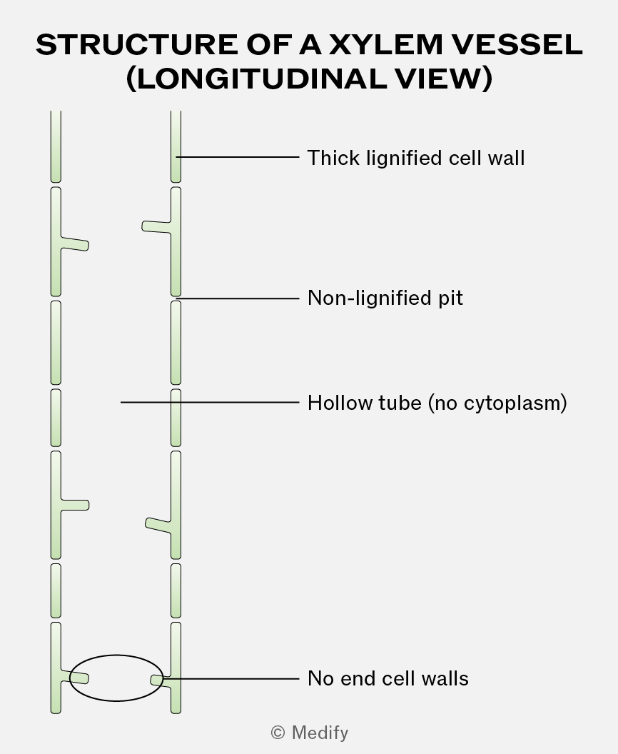
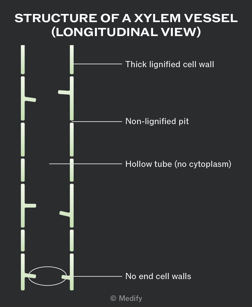
Xylem is a tissue made of cells joined end to end with no end walls between them. This creates a long, hollow tube structure that allows continuous, uninterrupted water transport.
The xylem cells that make up the vessels are dead, meaning they contain no cytoplasm or organelles. This gives the xylem an empty lumen, which reduces resistance to the flow of water.
The vessels are narrow, helping water rise by capillary action.
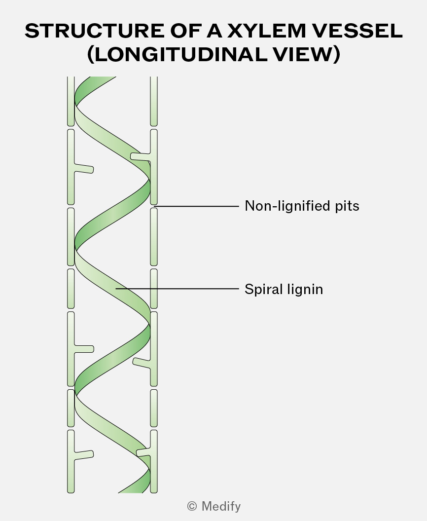
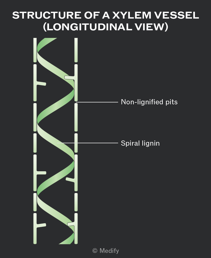
Xylem vessel walls are impregnated with spirals of lignin around the lumen of the vessel. The spiral pattern provides flexibility, while lignin provides support and additional mechanical strength, preventing the vessels from collapsing inwards under the tension generated during water transport.
Lignin is also waterproof, which minimises water loss from the vessel.
Pits within the walls of the xylem are non-lignified, allowing lateral movement of water between other cells and xylem vessels.
Water is essential in plants for both structural and metabolic reasons:
- It provides support and turgidity, helping cells maintain shape, and is used in photosynthesis to produce glucose and oxygen.
- Water acts as a solvent, dissolving mineral ions for transport in the xylem and assimilates (sugars) for transport in the phloem.
- Evaporation of water helps to keep the plant cool.
- It is a metabolite used in many hydrolysis reactions.
Water is absorbed into the root by osmosis, down a water potential gradient.
This gradient is established when mineral ions are actively transported from the soil into the cytoplasm of root hair cells, making the water potential inside the root lower than in the soil.
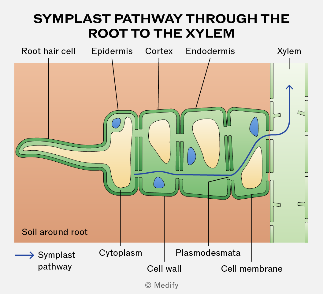
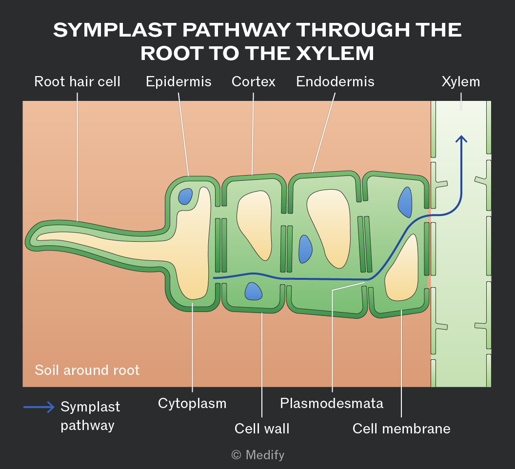
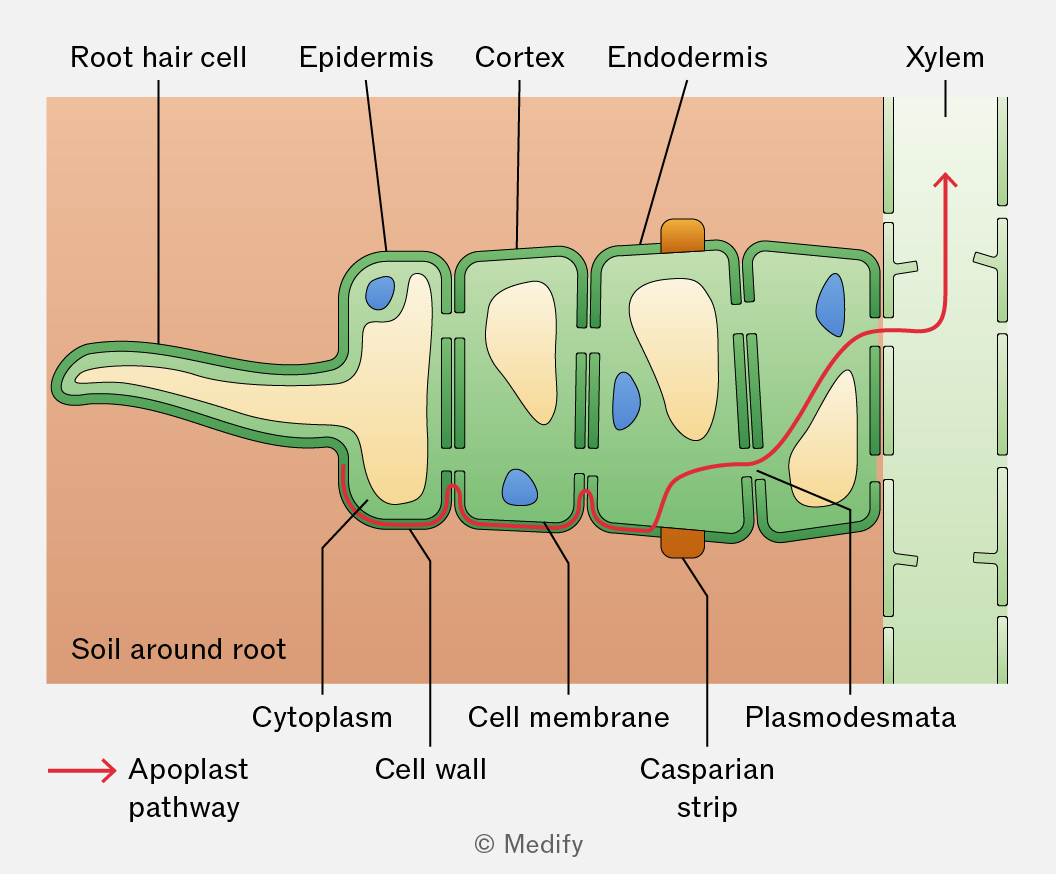
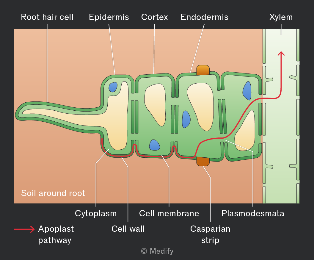
To reach the xylem, water moves from the root hair cells through the cortex and endodermis through one of two routes: the symplast or apoplast pathway.
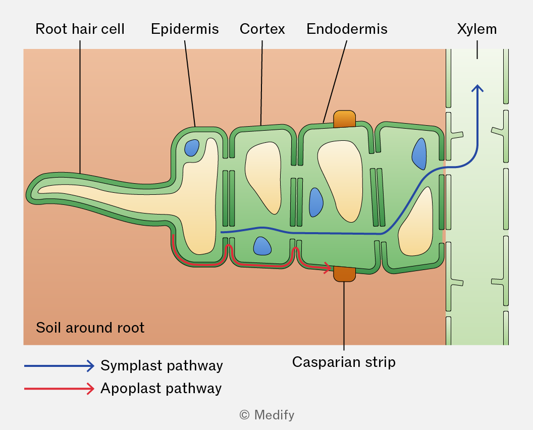
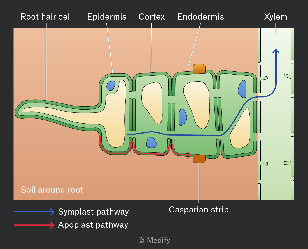
In the symplast pathway, water diffuses through the plasma membrane of root cells and enters the cytoplasm. It then moves from cell to cell through specialised cell junctions called plasmodesmata.
Water moves from a region of higher water potential to lower water potential by osmosis, down a water potential gradient.
This pathway is slow because entry into the pathway is regulated by crossing the plasma membrane of the root hair cell, which creates greater resistance to movement.
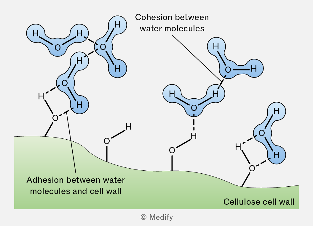
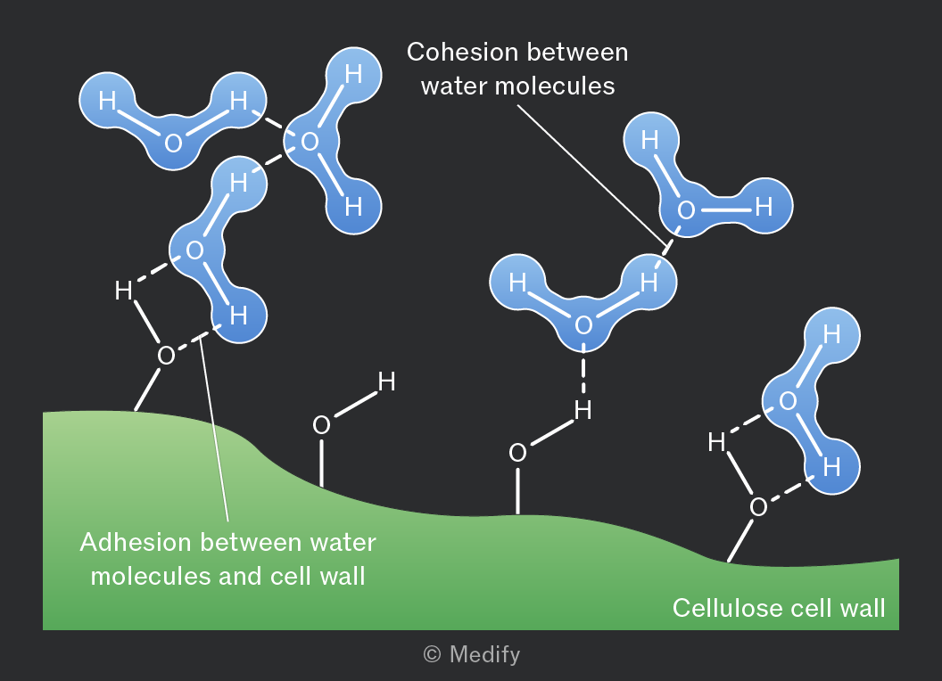
In the apoplast pathway, water moves between cells through the cell walls and intercellular spaces.
Water fills the spaces within the loose network of cellulose fibres in plant cell walls.
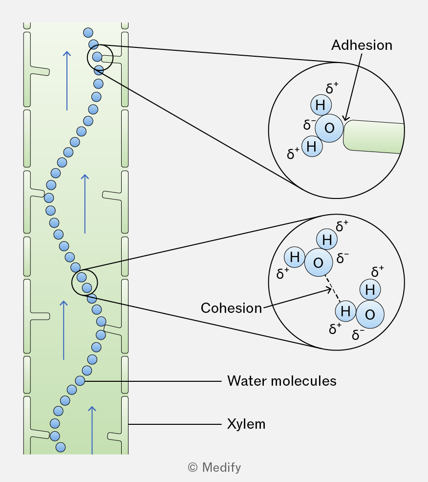
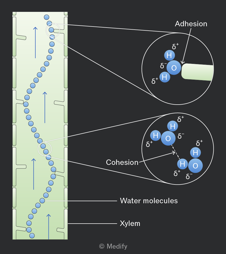
Adhesion occurs between water molecules and the cell walls, helping water move through the walls by capillary action.
Cohesion between water molecules also helps pull additional water molecules along.
Water moves down a pressure gradient by mass flow. This pathway is faster because water does not initially cross cell membranes.
When water moving through the apoplast pathway reaches the endodermis, it is blocked by a waterproof barrier called the Casparian strip. This strip contains suberin, which prevents water from continuing through the cell walls.
As a result, water must enter the cytoplasm of the endodermal cells, forcing it into the symplast pathway before it can enter the xylem.
Crossing the plasma membrane at this point allows the plant to control which substances enter the xylem, preventing harmful or toxic substances from being transported.
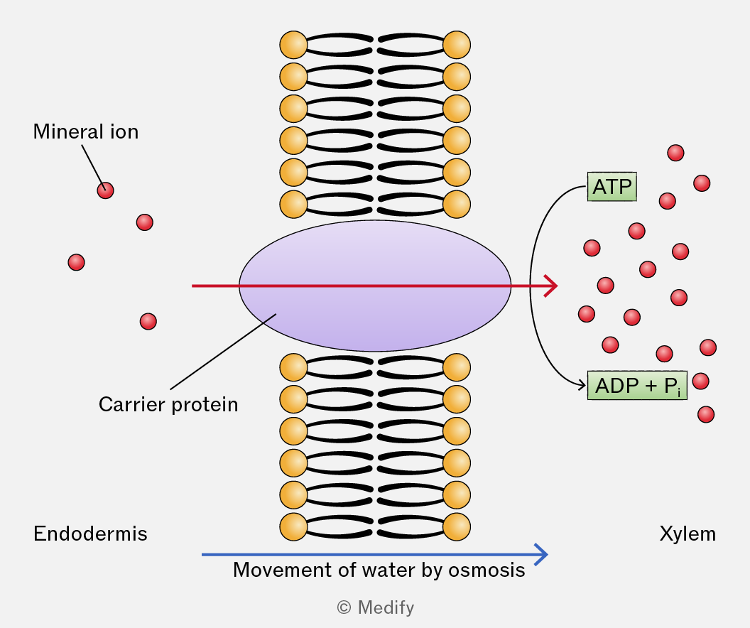
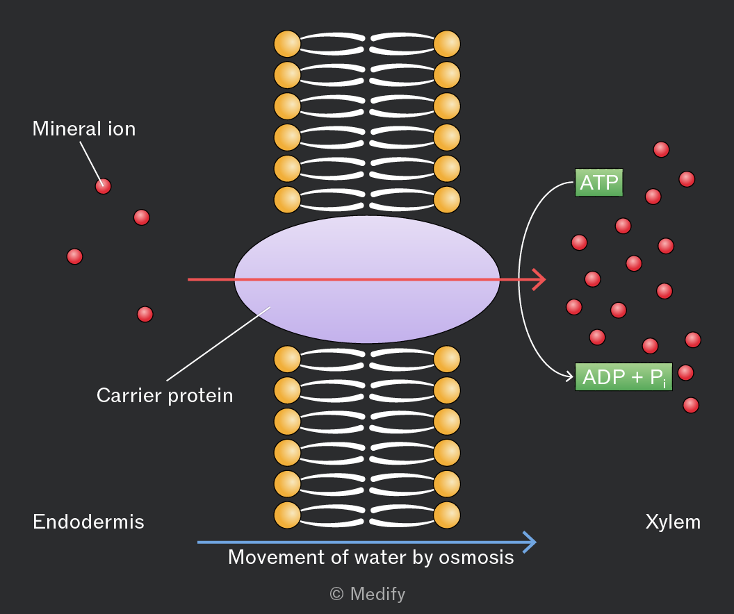
Mineral ions are actively pumped into the xylem vessels from the endodermis of the roots against their concentration gradient using carrier proteins / ion pumps, which requires ATP.
By lowering the water potential in the xylem, water moves in from the endodermis through the symplastic pathway by osmosis.
The inflow of water generates pressure, giving the water a small push upward in the xylem.
Stomata are pores mainly on the underside of leaves that allow carbon dioxide to enter and oxygen to leave the plant.
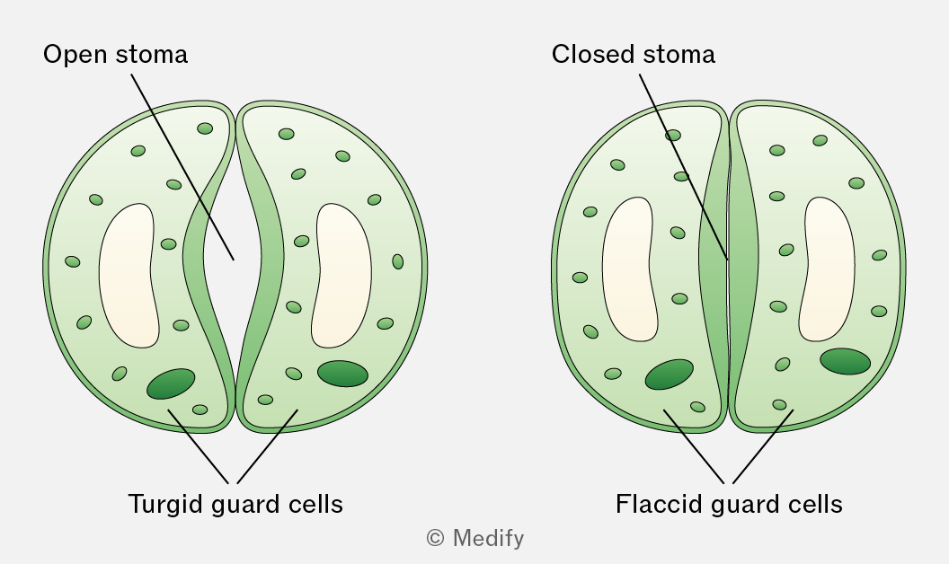
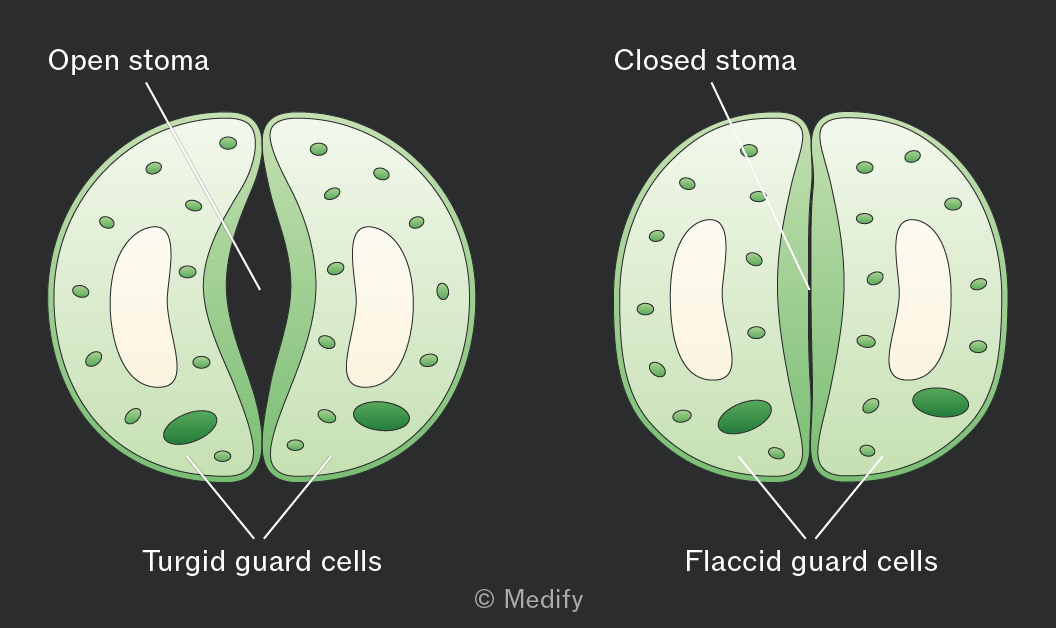
Each stomatal pore is surrounded by kidney-shaped guard cells with a thicker inner wall and thinner outer wall.
When guard cells take in water and become turgid, they swell and bend, opening the stomata. This happens during the day when photosynthesis occurs in the presence of sunlight.
When guard cells lose water and become flaccid, the stomata close. This happens at night when photosynthesis cannot occur.
Transpiration is the loss of water vapour from a plant by evaporation from the leaf and diffusion into the atmosphere through the stomata.
It occurs as a consequence of gas exchange through the stomata.
Water evaporates from the surfaces of the spongy mesophyll cells into the air spaces within the leaf and then diffuses out of the leaf through the open stomata down a water vapour potential gradient.
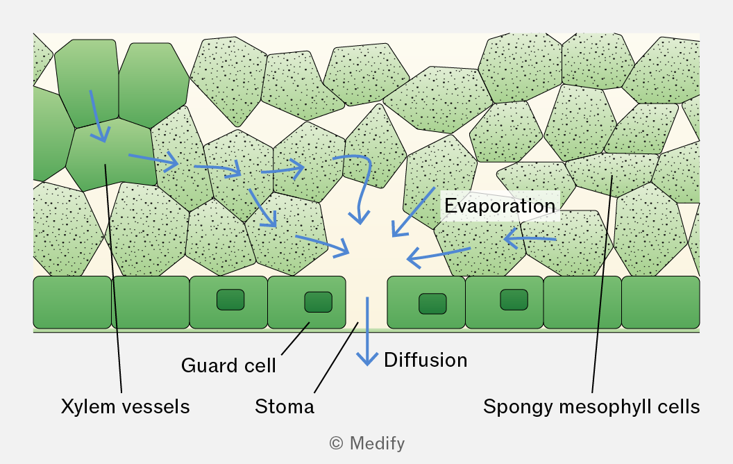
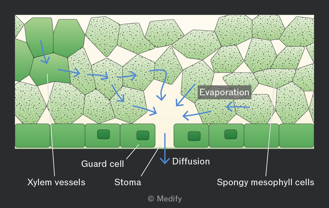
The transpiration stream is the movement of water from the roots to the leaves through the xylem in the stem. This process is explained by the cohesion–tension theory.
In the cohesion–tension theory, transpiration reduces the water potential in the mesophyll cells, causing water to move by osmosis from the xylem into these cells. This creates tension (negative pressure) in the xylem, causing water to move down a pressure gradient by mass flow from roots to leaves.
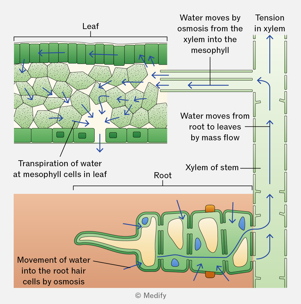
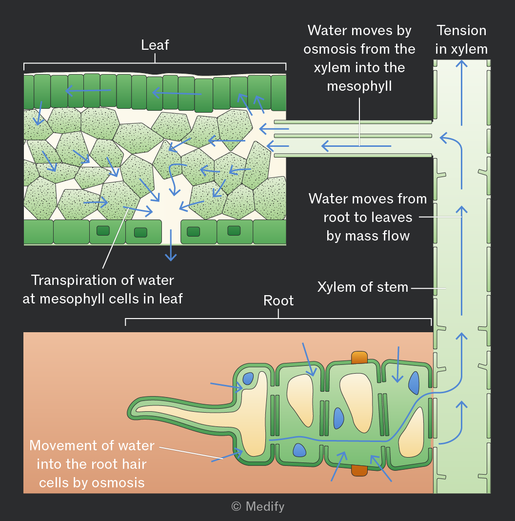
In the cohesion–tension theory, the cohesion between water molecules, forms a continuous column of water in the xylem, which is pulled upwards as a result of the tension created by transpiration.
Adhesion occurs between water molecules and the walls of the xylem vessels, helping the water column move up the vessel by capillary action and resist the effects of gravity.
Increased light intensity increases the rate of transpiration.
This is because light increases the rate of photosynthesis, causing stomata to open to allow carbon dioxide to enter the leaf for gas exchange.
When the stomata open, more water vapour can diffuse out of the leaf, increasing evaporation from the mesophyll cells and loss of water through the stomata.
Humidity is a measure of the amount of water vapour in the air.
Increased humidity decreases the rate of transpiration because it reduces the water vapour potential gradient between the inside of the leaf and the surrounding air.
Increased temperature increases the rate of transpiration by raising the kinetic energy of water molecules, increasing the rate of evaporation from the spongy mesophyll cells and the rate of diffusion of water vapour out of the stomata.
Increased air movement increases the rate of transpiration.
This is because water vapour around the stomata is blown away. This lowers the water vapour potential around the stomata, increasing the water vapour potential gradient between the air spaces in the leaf and the outside air. As a result, water vapour diffuses out of the leaf at a faster rate.
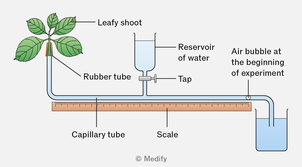
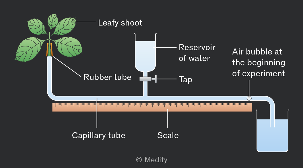
A potometer is an apparatus that measures a plant’s water uptake. It is assumed that water uptake is directly related to water loss by the leaves, and therefore, it can be used to measure the rate of transpiration.
Potometers have limitations:
- Not all water uptake is lost in transpiration. Some water is used to maintain turgidity and support in cells and for photosynthesis.
- The rate of water movement through a shoot does not accurately reflect that in a whole plant, because plants have roots.
- The xylem vessels in a shoot are much narrower than the capillary tube in the apparatus.
To correctly set up a potometer:
- The stem should be cut, the apparatus assembled, and the stem inserted into the apparatus under water. All joints must be sealed so the potometer is airtight and watertight.
These precautions prevent air bubbles from entering the xylem, which could block the vessels and break the continuous column of water. The sealing of joints also reduces the loss of water vapour and prevents the entry of pathogens. - The stem should be cut at a slant / angle to increase the surface area for water uptake into the xylem.
- The leaves should be dried before readings are taken so that no excess water droplets are on the surface of the leaves.
- The water reservoir tap should remain closed during the investigation to prevent water from entering the capillary tube.
Precautions to take whilst using a potometer:
- Keep the open end of the apparatus in water so that no air bubbles are introduced.
- Keep the shoot still and supported to avoid breaking the seals of the potometer or the water column in the xylem.
- Do not allow the air bubble to move too far along the capillary tube. Use the tap or reservoir to move the bubble back to the starting position when repeating the investigation. This prevents the air bubble from entering the xylem and allows the same bubble to be reused for reliable measurements.
To use a potometer:
- Remove the end to form a single air bubble and note its starting position.
- Measure the distance the bubble travels over time.
- Repeat at least three times to identify anomalies, then calculate the mean distance moved by the air bubble.
Keep all other conditions constant: use the same plant species (ideally the same plant each time) and ensure the number and size of leaves remain the same, controlling for stomatal density and surface area.
To calculate the rate of transpiration using a potometer, you calculate the volume of water taken up by the plant per unit time.
The formula is below:
Where:
- = radius of the capillary tube
- = cross-sectional area of the capillary tube
- = distance travelled by the air bubble
- =time taken
Units are typically or depending on the measurements used.
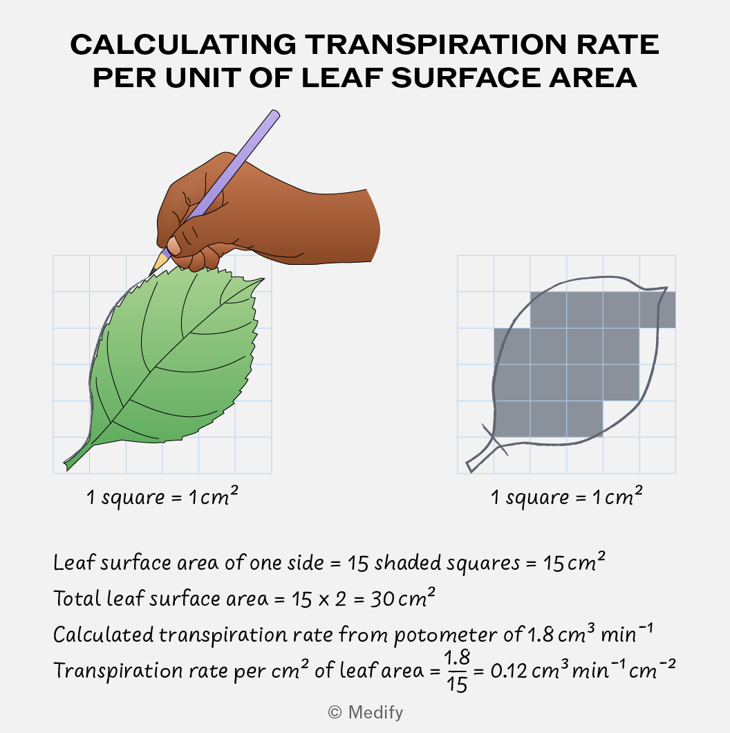
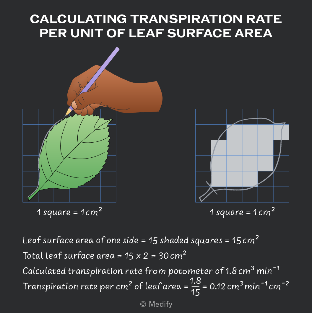
To estimate the rate of transpiration per of leaf surface area:
- Flatten the leaves onto graph paper and draw around the leaf.
- Count the number of squares covered by the leaf, including only squares that are more than 50 covered.
- Double the leaf area to account for both the upper and lower leaf surfaces.
- Divide your calculated transpiration rate by the leaf area to get the rate per .
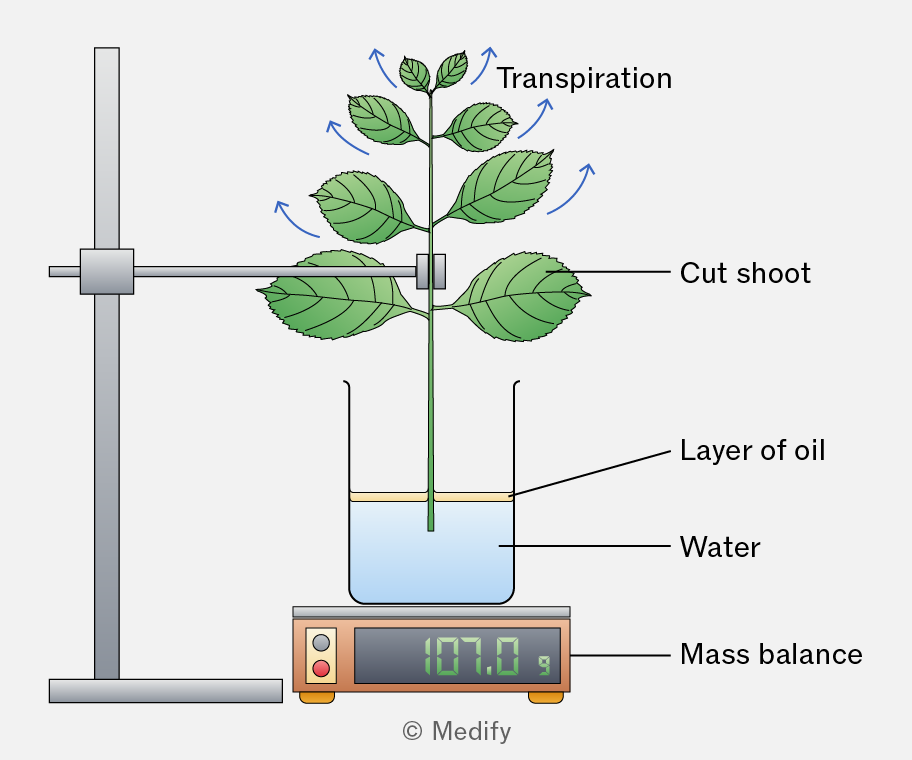
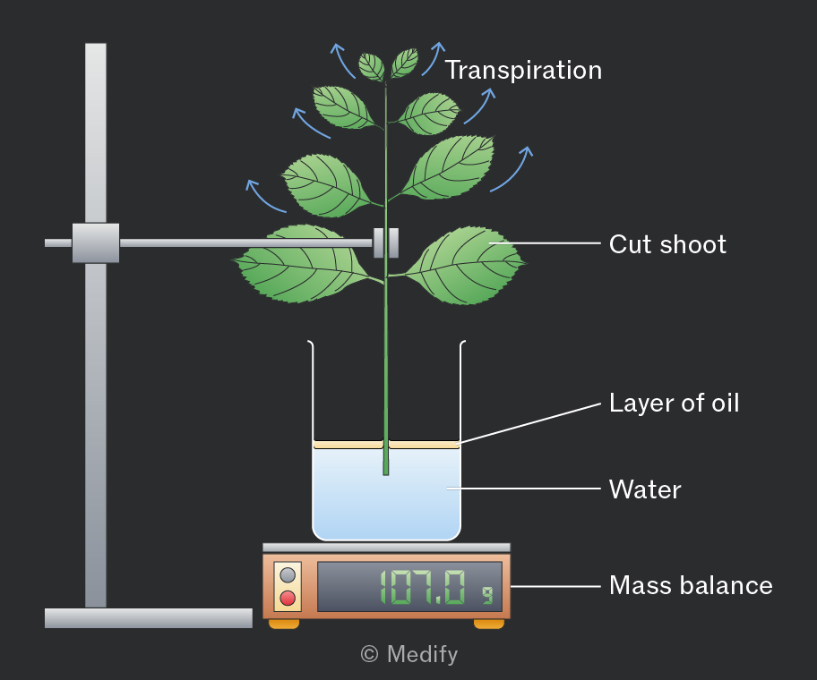
The rate of transpiration can be measured by recording the mass loss of a plant over time.
The plant is placed on a mass balance and weighed at regular intervals. As water evaporates from the leaves, the plant’s mass decreases, giving an estimate of the transpiration rate.
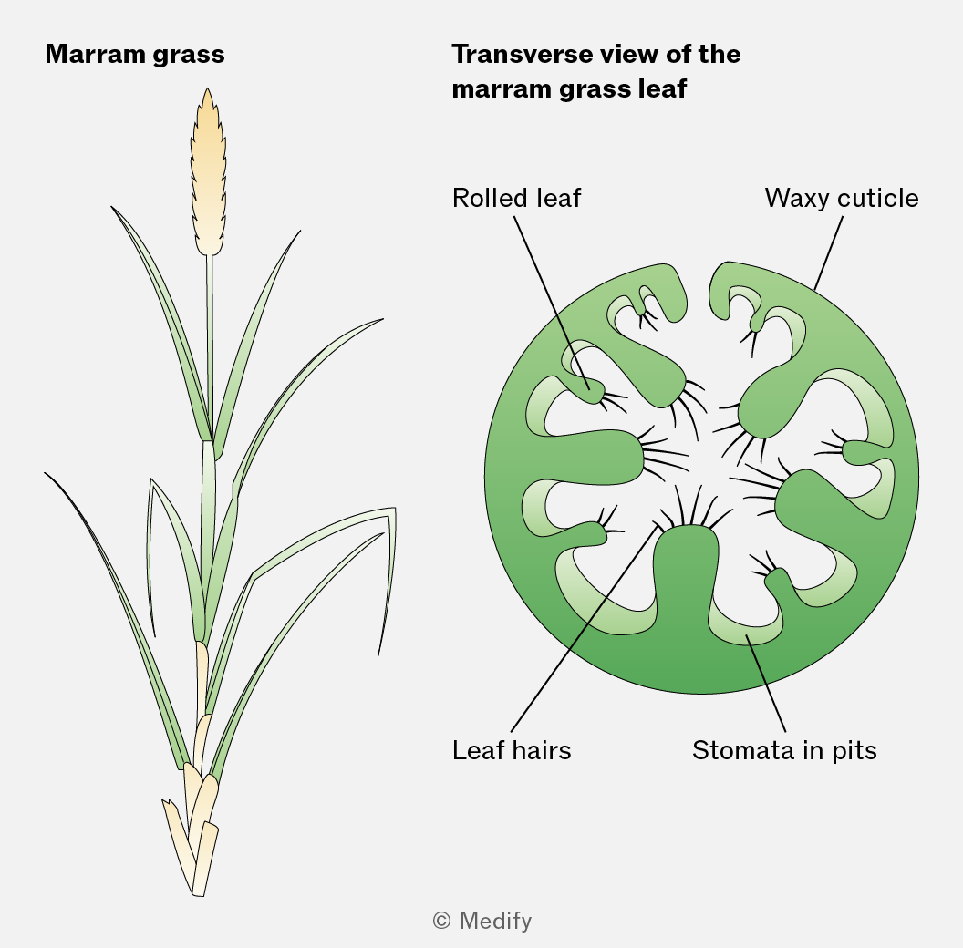
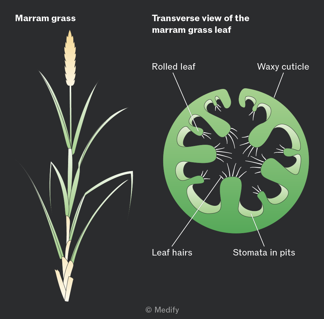
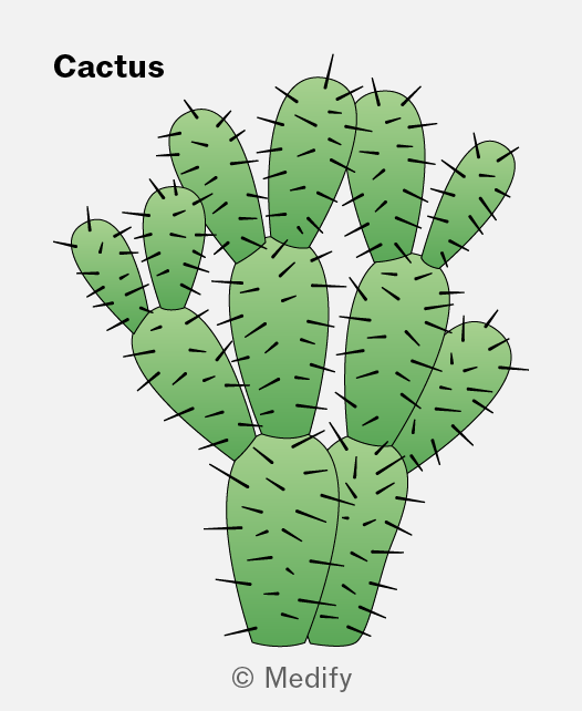
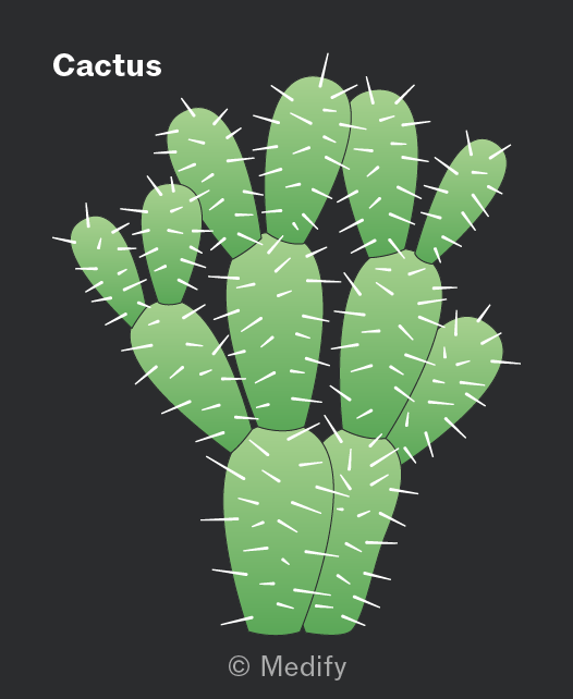
Xerophytes are plants that live in dry environments, such as deserts or sand dunes. They require adaptations to reduce water loss and conserve water. Examples of xerophytes include cacti and marram grass.
Xerophytes have several adaptations to reduce water loss.
Marram grass has sunken stomata, leaf hairs, and rolled leaves, which help reduce transpiration by:
- reducing air movement and trapping water vapour, increasing humidity around the stomata. This lowers the water potential gradient between the leaf and the surrounding air, reducing water loss.
- reducing the surface area exposed for transpiration.
Xerophytes have several adaptations to reduce water loss.
Cacti reduce water loss by:
- Having spines instead of leaves, reducing their surface area:volume ratio and therefore reducing transpiration.
- Closing their stomata during the hottest part of the day.
- Having a thick, waxy cuticle, which is waterproof. Its thickness increases the diffusion distance, while the wax layer reduces evaporation from the leaf surface.
Hydrophytes are plants which live in aquatic environments, such as water lilies.
Given that water is abundant in their environment, adaptations to reduce water loss are not needed.
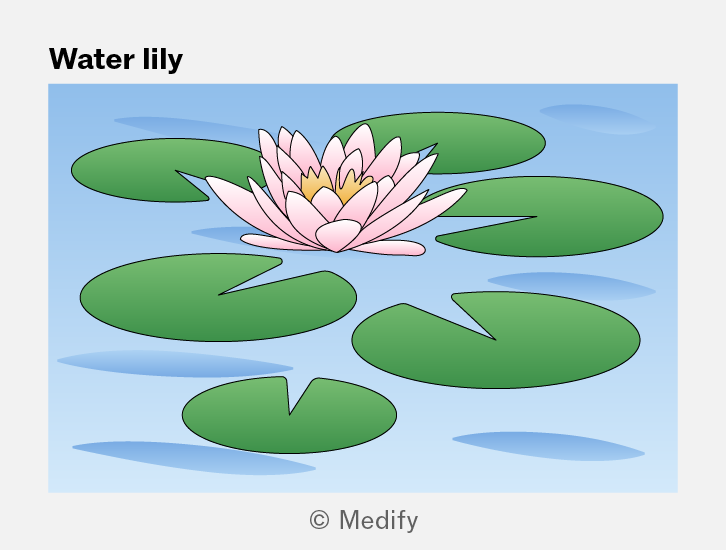
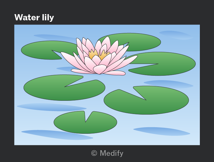
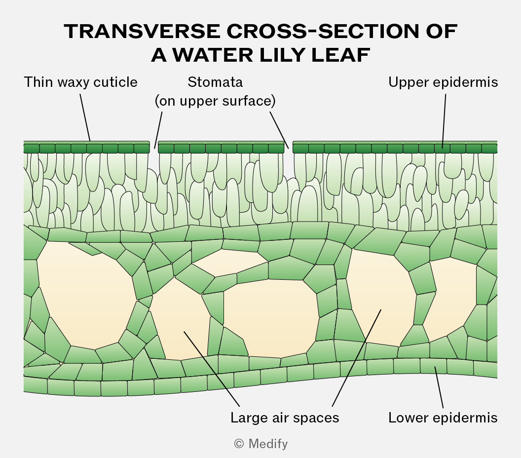
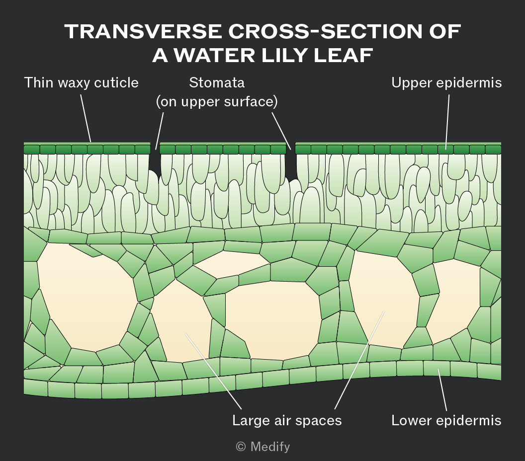
Hydrophytes have large air spaces in their leaves and stems, which help them float on water and increase the amount of light they receive for photosynthesis. These air spaces can also store oxygen for respiration.
The stomata are mainly located on the upper surface of the leaf, allowing gas exchange to occur with the air, where the carbon dioxide concentration is higher.
Hydrophytes have flexible stems and leaves, which are supported by the surrounding water and can bend with water movement, preventing damage.
The waxy cuticle of the leaf is very thin or absent because water loss by transpiration is not an issue.
The leaves have a large surface area to maximise photosynthesis. They may also have a large number of stomata, which can remain open for longer periods to maximise gas exchange.
The function of the phloem is the movement of assimilates (such as sucrose, amino acids, hormones and salts), which are dissolved in water from source (site of production) to sink (site of usage). This process is called translocation and it requires energy.
Translocation is a two-way flow, moving assimilates both up and down the plant by the process of mass flow, down a pressure gradient.
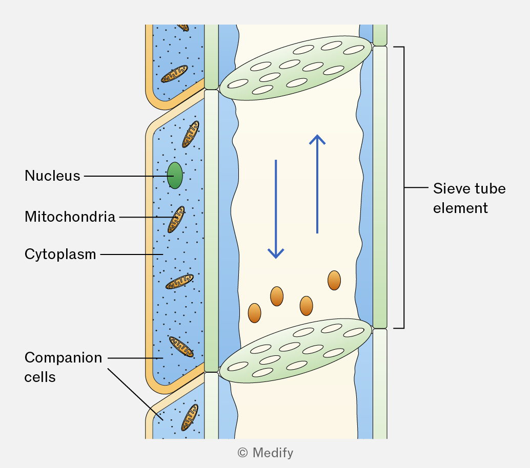
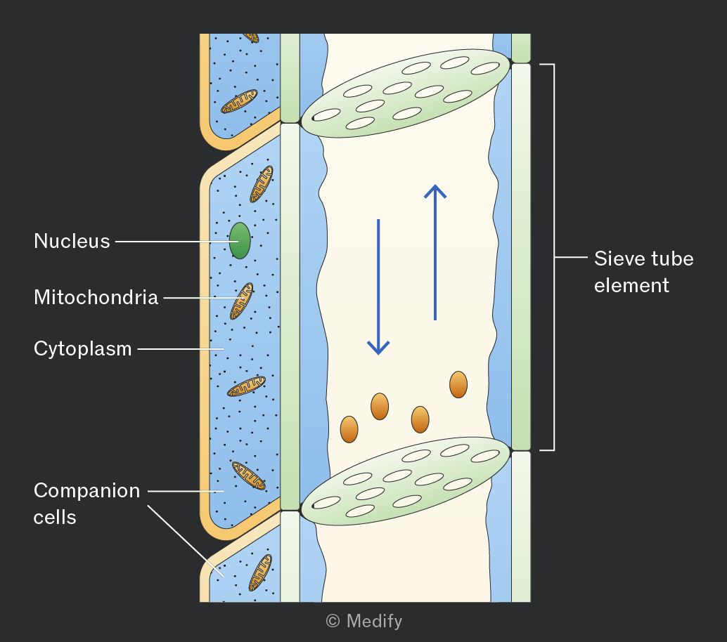
Phloem is a tissue made of two types of cells – sieve tube elements and companion cells.
Sieve tube elements are cells stacked end to end to form long, hollow, continuous tubes, which allow mass flow of assimilates with minimal resistance. Although sieve tube elements are living cells, they contain very little cytoplasm, no nucleus, and few organelles, further reducing resistance and facilitating the flow of substances.
The end walls of sieve tube elements, called sieve plates, contain pores that allow assimilates to pass through and connect the cytoplasm of adjacent cells. The sieve plates also limit the size of molecules that can pass and slightly reduce the rate of flow.
The cell walls of sieve tube elements are thin, not lignified (cellulose only), and do not contain pits.
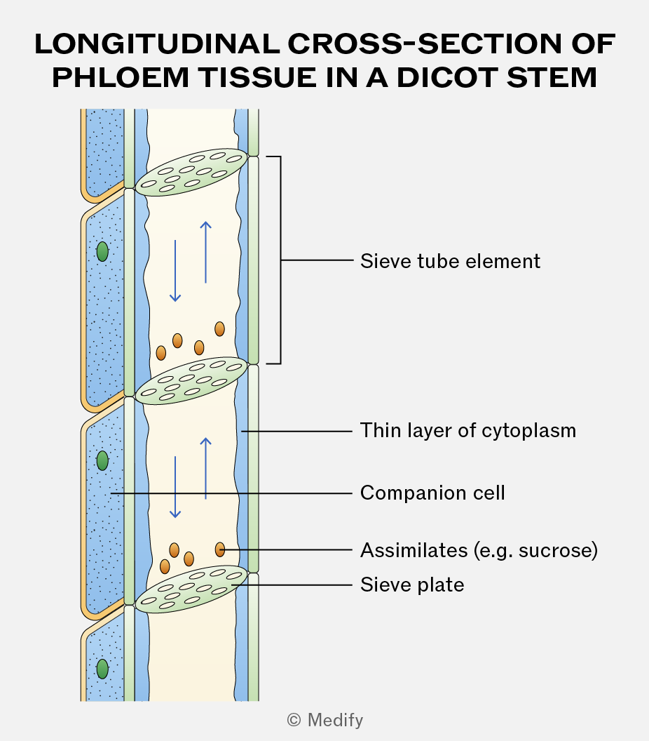
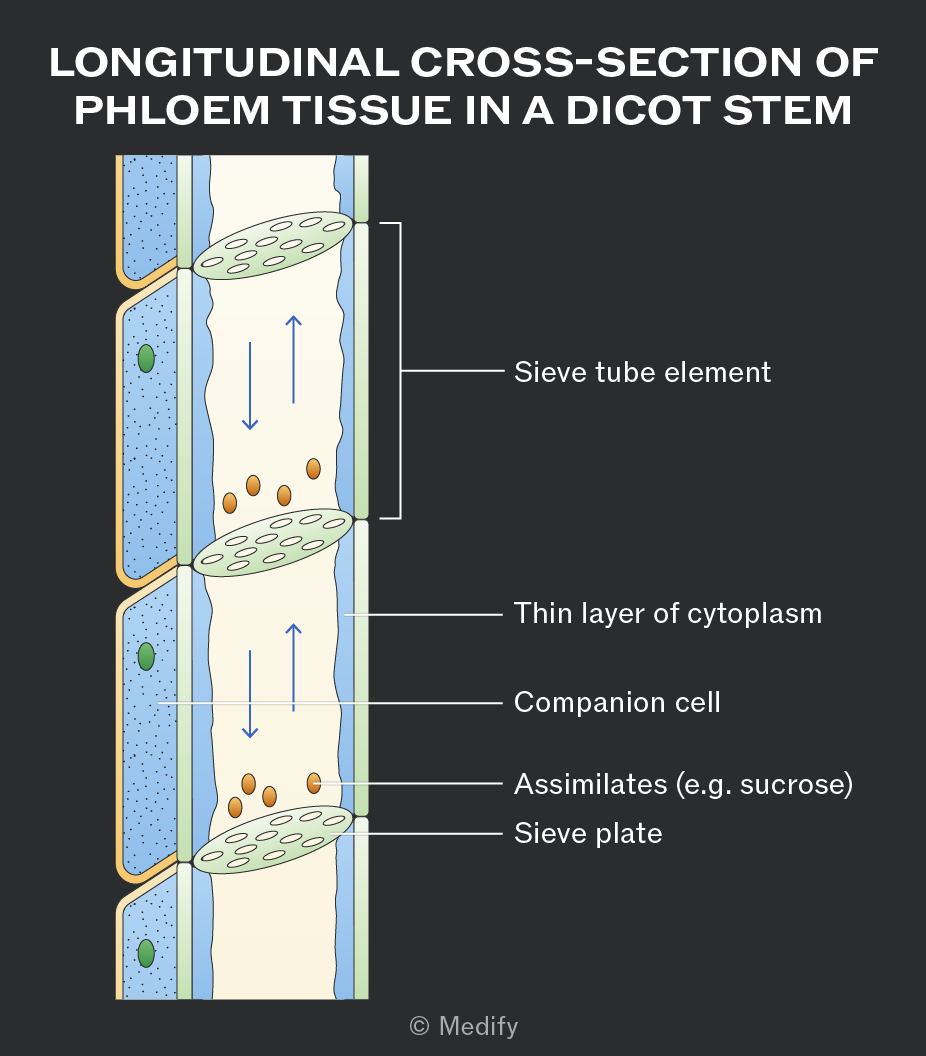
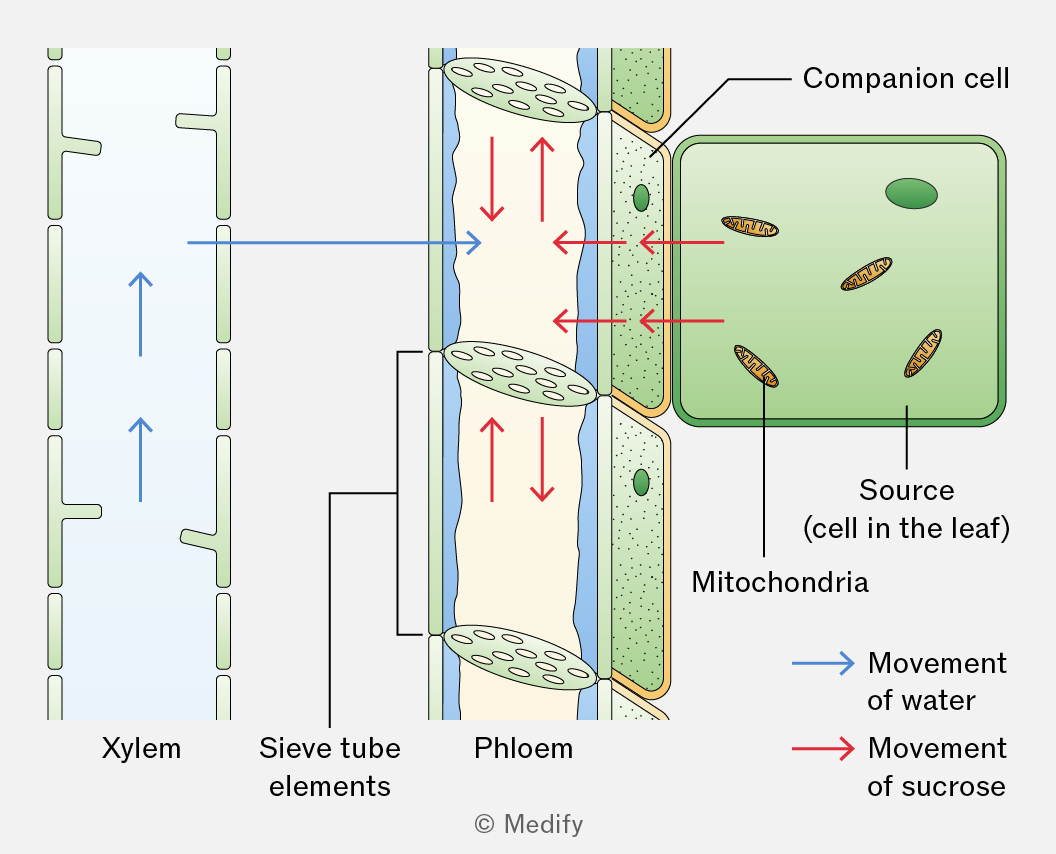
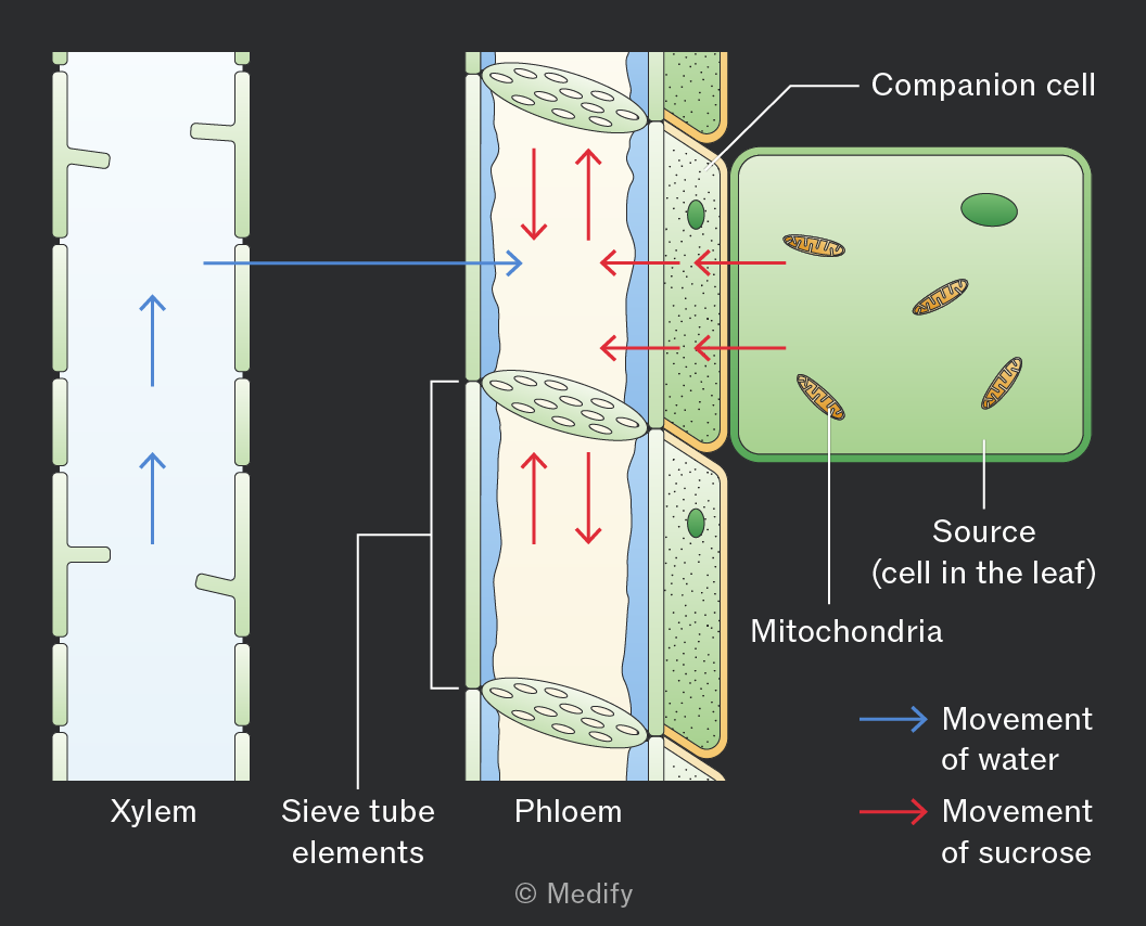
Companion cells act as the “life support” for sieve tube elements, carrying out the living functions. They contain dense cytoplasm, a large nucleus, and many mitochondria, and are connected to the sieve tube elements via plasmodesmata.
The mitochondria and other organelles provide energy for active transport, allowing the companion cells to load sucrose from the source (where assimilates originate) into the sieve tube elements through active loading.
A source is a part of the plant where assimilates are produced.
Examples include green leaves, storage organs such as tubers that are unloading their stores, and food reserves in germinating seeds.
Glucose produced in photosynthesising cells is converted into an assimilate, such as sucrose, for translocation in the phloem.
Sucrose is soluble, allowing it to move in sap, and relatively metabolically inactive, so it is not used in respiration. Transportation as sucrose also reduces diffusion out of the sieve tubes, as entry and exit are controlled by transport proteins.
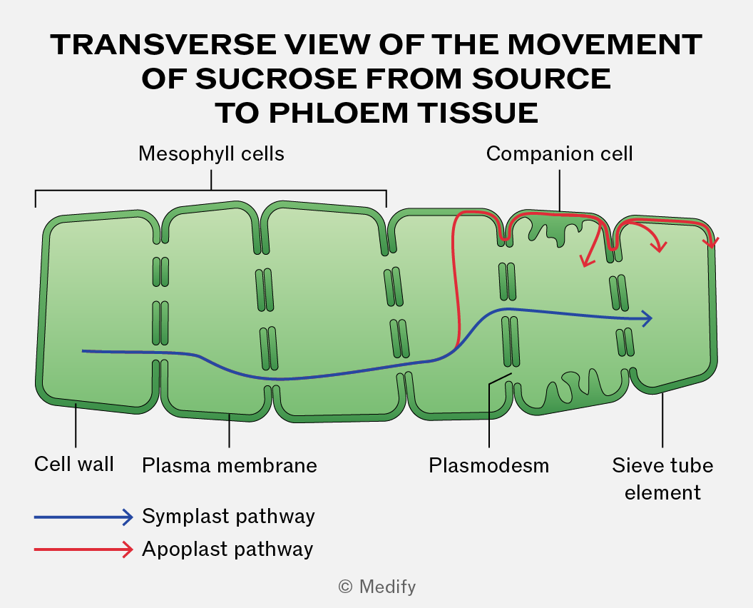
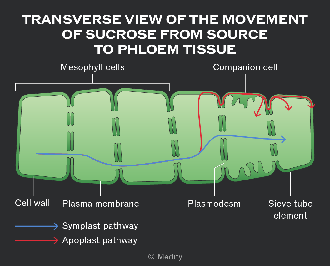
Sucrose moves between leaf cells via the passive symplast pathway through plasmodesmata or the active apoplast pathway through cell walls and intercellular spaces.
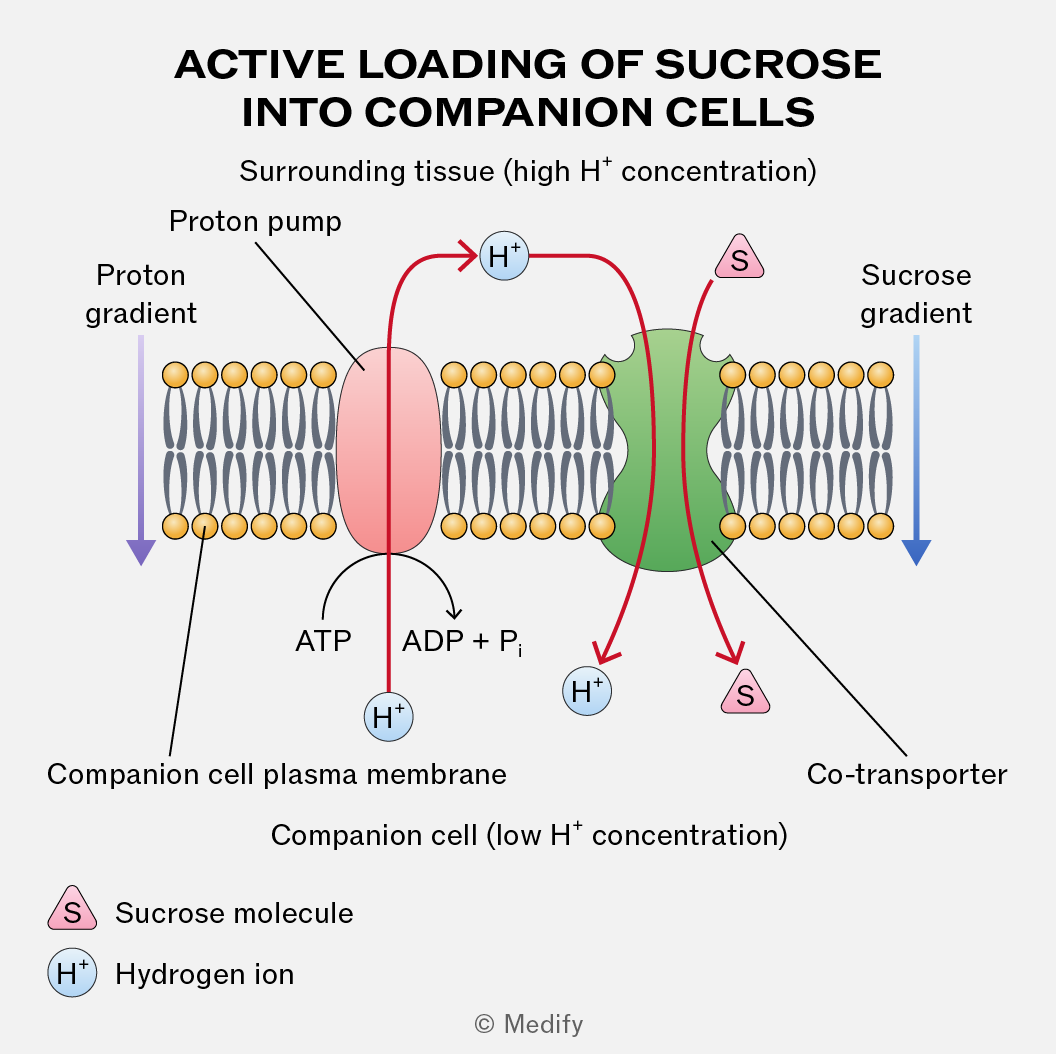
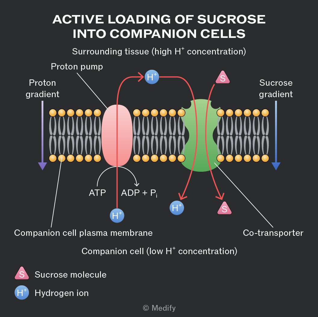
For the active loading of sucrose into the companion cells from the surrounding tissue, protons
() are actively pumped out using ATP and a proton pump. This creates a proton gradient.
Protons then re-enter the cell via co-transport proteins, carrying sucrose molecules with them. This process actively loads sucrose into companion cells, from where it diffuses into sieve tube elements for translocation.
The entry of sucrose into sieve tube elements at the source decreases the water potential in the sieve tube elements. This causes water to enter the phloem by osmosis from the surrounding cells and xylem vessels. This results in higher hydrostatic pressure within the sieve tube elements.
When the sucrose arrives at the sink, it diffuses out of the sieve tube elements into the surrounding cells. This causes the water potential inside the sieve tube elements to increase so water leaves by osmosis down a water potential gradient. This lowers the hydrostatic pressure.
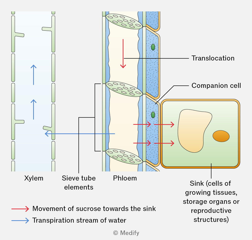
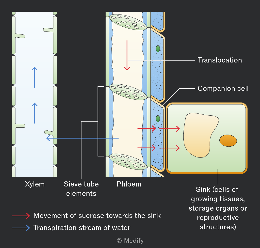
A hydrostatic pressure gradient drives the mass flow of sucrose dissolved in water from source to sink. The high hydrostatic pressure in the phloem at the source enables rapid transport over long distances.
A sink is a part of a plant where assimilates are used or stored. Assimilates are translocated from source to sink down a concentration gradient in the phloem. At the sink, assimilates are converted into glucose for respiration or starch for storage, maintaining a concentration gradient between the phloem and cells.
Examples include growing roots, dividing meristems, developing seeds, fruits, or storage organs.
Some parts of the plant can act as both a source and a sink, storing and releasing carbohydrates as needed.
For example, roots or leaves may act as a source or a sink at different times of the year.