
Bonding (Topic 2A)
On this page
Ionic bonding is a type of chemical bonding that occurs between metals and nonmetals.
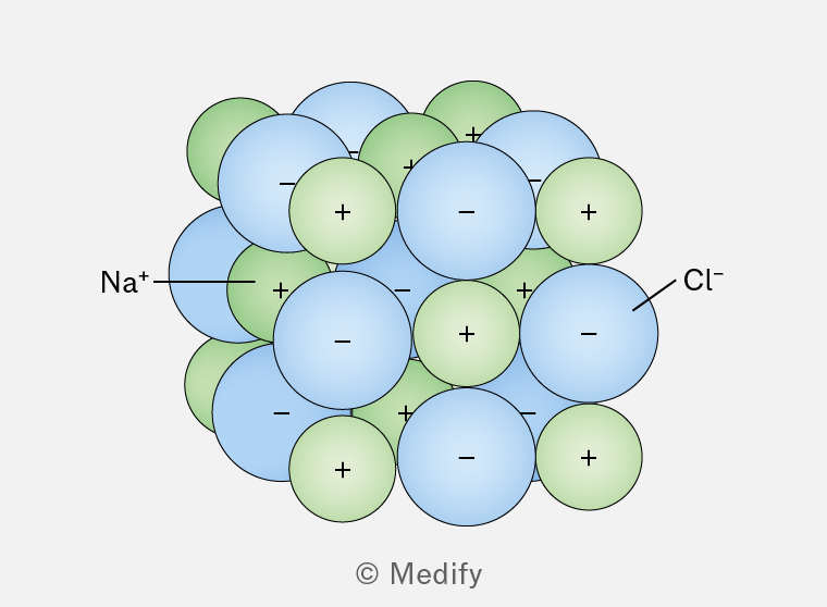
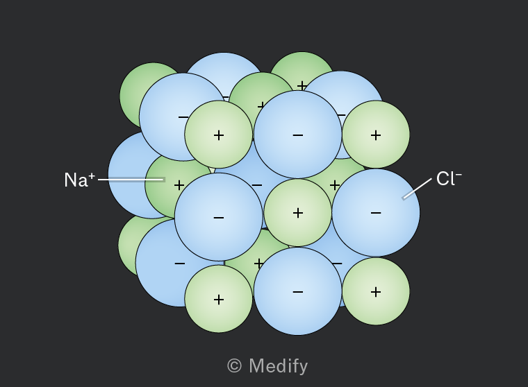
Ionic bonding involves the initial transfer of electrons from one atom to another, resulting in the formation of positive and negative ions.
There is an electrostatic force of attraction between the positively charged cations and the negatively charged anions.
This force is strong and extends in all directions, forming a giant ionic lattice structure.
The melting and boiling points of ionic compounds vary.
Compared to sodium chloride , which has a melting point of and a boiling point of , magnesium oxide has a much higher melting point of and a boiling point of .
This can be explained by the influence of ionic charge and ionic radius.
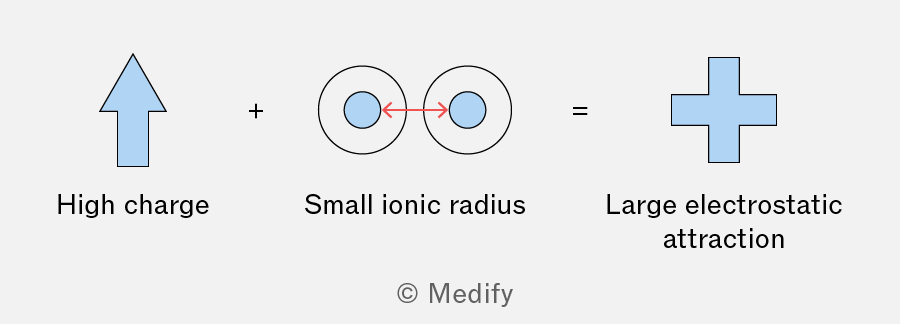
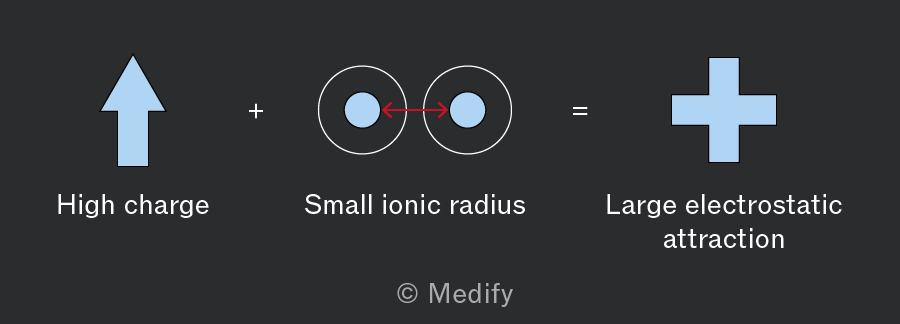
Charge of the ions: higher charges on the ions result in stronger electrostatic forces of attraction.
Size of the ions: smaller sized ions can pack more closely together, increasing the electrostatic forces of attraction between them.
Ions are formed when atoms lose or gain electrons.
Metals (for example, sodium, ) tend to lose electrons, forming positive ions (cations).
Non-metals (for example, chlorine, ) tend to gain electrons, forming negative ions (anions).
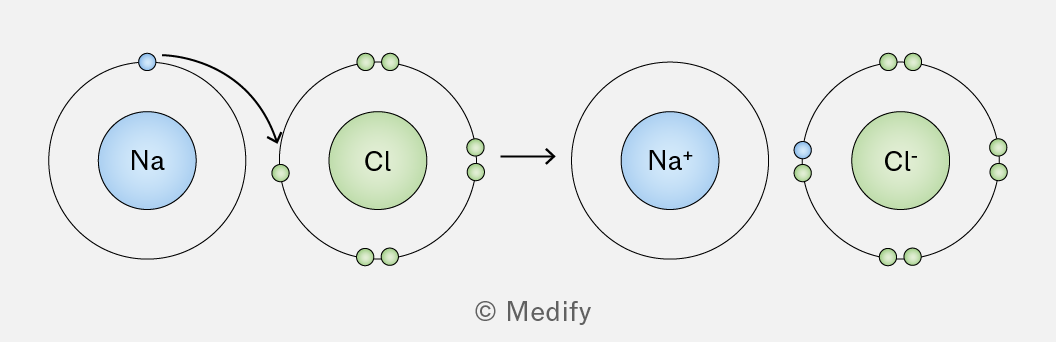
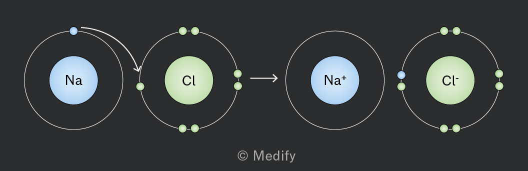
For example:
- a sodium atom loses one electron to form a ion
- a chlorine atom gains one electron to form a ion.
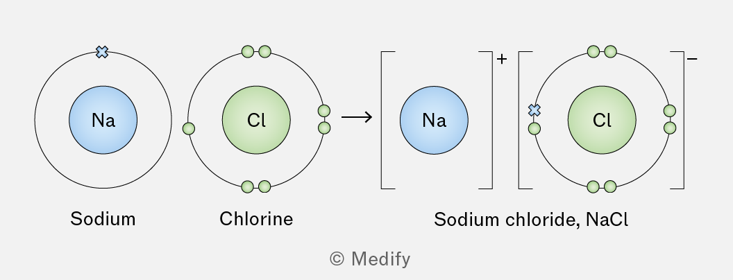
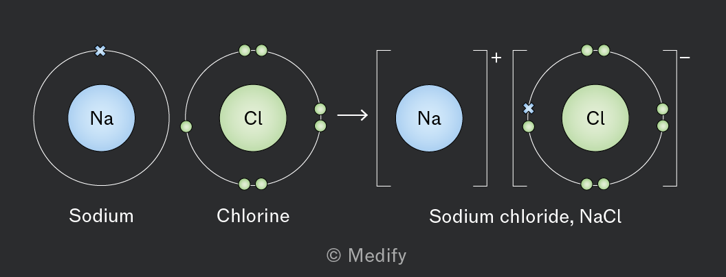
To construct a dot cross diagram for sodium chloride:
- Identify the outer shell electrons.
- has one outer shell electron .
- has seven outer shell electrons .
- Transfer the electron from to .
- loses its electron to become .
- gains one electron to fill its orbital, becoming .
- Draw the ions with their new electron arrangements.
- ion: no outer shell electrons shown since the electron is lost.
- ion: eight outer shell electrons (represented as dots and crosses).
Sodium chloride is a common example of a giant ionic lattice.
In this structure, each sodium ion is surrounded by six chloride ions , and each chloride ion is surrounded by six sodium ions.
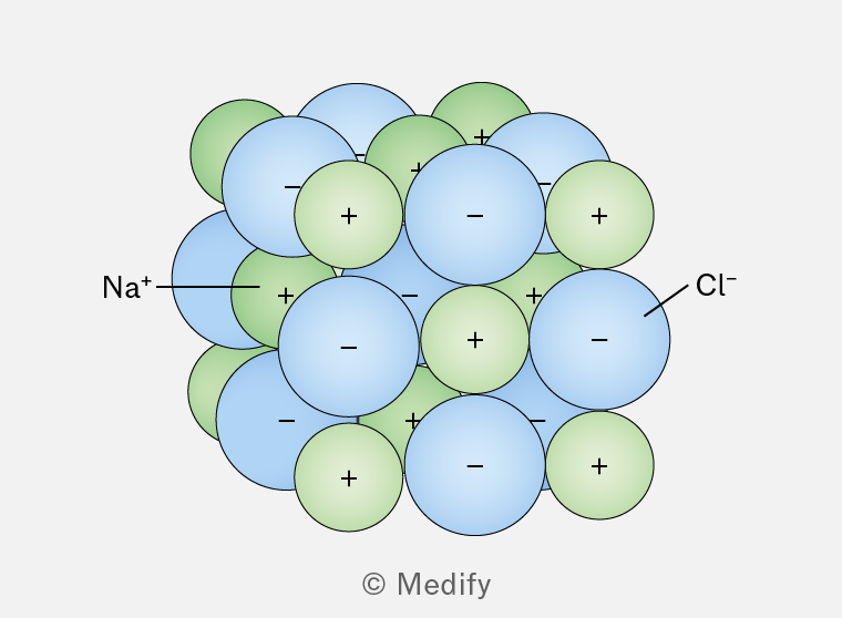
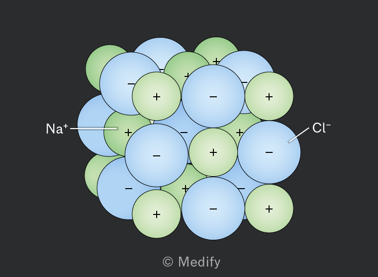
and ions alternate in a three-dimensional lattice structure.
Ionic compounds typically have high melting and boiling points.
This is due to the strong electrostatic forces of attraction between the oppositely charged ions in the giant ionic lattice.
A significant amount of energy is required to overcome these forces and change the compound from solid to liquid (melting) or from liquid to gas (boiling).
The ability of ionic compounds to conduct electricity relies on the ability of the ions to move and carry charge, which depends on the state they are in:
- In the solid state, ionic compounds do not conduct electricity because the ions are fixed in the lattice and cannot move freely, and therefore cannot carry charge through the giant ionic lattice.
- When molten, ionic compounds become good conductors of electricity. The ions move freely in the liquid state, allowing them to carry charge.
- Ionic compounds also conduct electricity when dissolved in water. The ions dissociate and move freely in the solution, allowing them to carry charge.
Question walkthrough
Dot cross diagrams
Draw dot cross diagram for ionic compound
A covalent bond is characterised by the strong electrostatic attraction between a shared pair of electrons and the nuclei of the bonded atoms.
The shared electrons are attracted to the positively charged nuclei of both atoms, holding the atoms together.
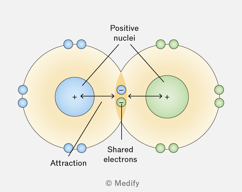
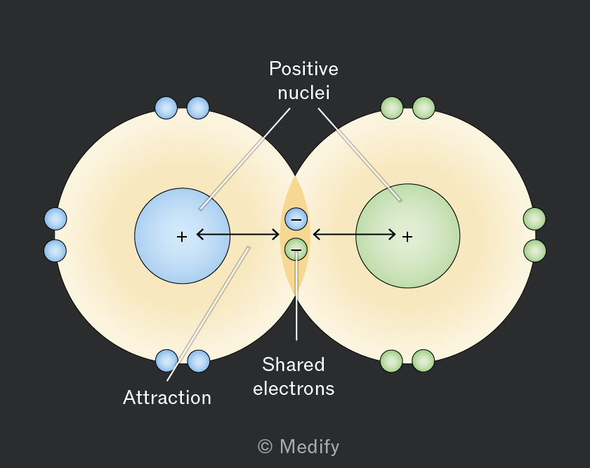
The number of shared electron pairs determines the type of covalent bond:
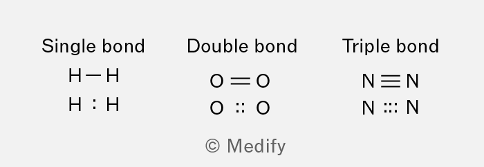
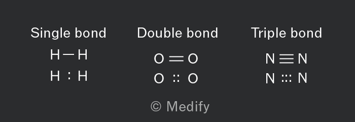
- Single bond: one pair of electrons is shared, for example and .
- Double bond: two pairs of electrons are shared, for example and .
- Triple bond: three pairs of electrons are shared, for example and .
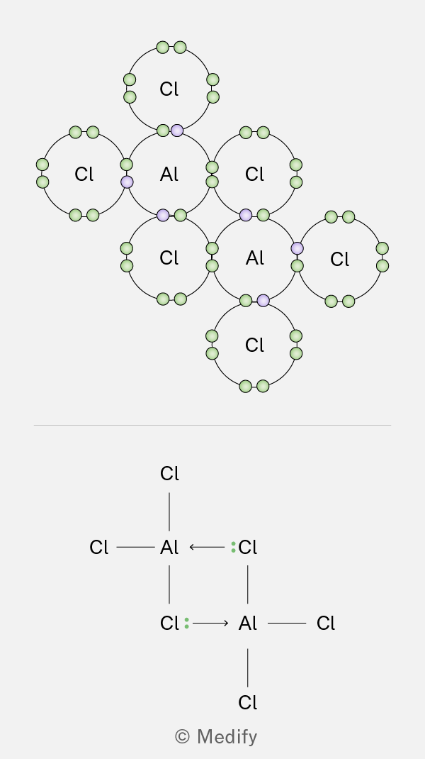
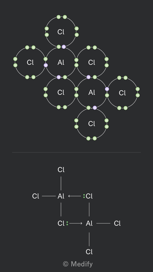
A dative covalent bond, or coordinate bond is a special type of covalent bond where one atom provides both electrons in a shared pair.
Dative covalent bonds, or coordinate bonds can be shown in a dot cross diagram through the use of atom specific electron markers, or in line representation using an arrow as shown in the dimerised form of .
A dimer is a molecule or molecular complex consisting of two identical molecules linked together.
Question walkthrough
Dot-cross diagrams
Draw dot-cross diagram for covalent compound
Question walkthrough
Dot-cross diagrams
Draw dot-cross diagram featuring a dative covalent bond
Average bond enthalpy is the average energy needed to break one mole of a given covalent bond in a gaseous molecule: they are always endothermic and the units are .
The higher the average bond enthalpy, the stronger the bond, this means that more energy is required to break the bond, usually indicating lower reactivity.
The lower the average bond enthalpy, the weaker the bond, this means that less energy is required to break the bond, usually indicating higher reactivity.
In general shorter covalent bonds are stronger, and harder to break.
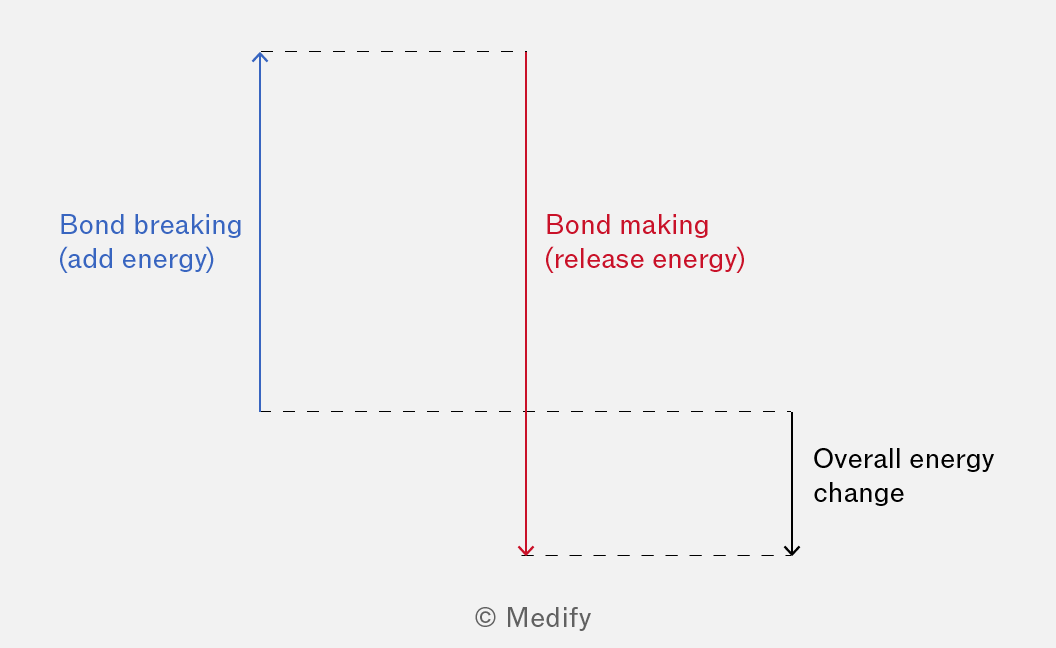
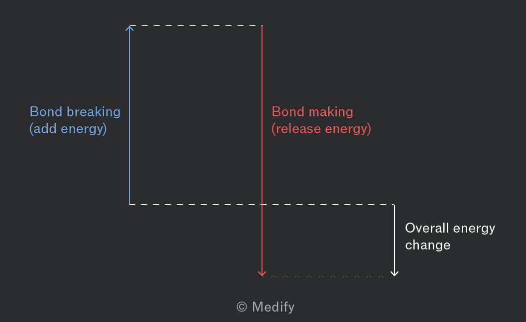
In chemical reactions, breaking bonds requires energy (endothermic process), and forming new bonds releases energy (exothermic process).
Bonding electrons and lone pairs repel each other because they are both regions of negative charge.
The shape of a molecule, or ion, is determined by the number of electron dense regions surrounding the central atom.
These regions repel each other and arrange themselves as far apart as possible to minimise repulsion. This principle is known as the electron pair repulsion theory (also called VSEPR – valence shell electron pair repulsion theory).
Both bonding regions and lone pairs impact the bond distribution, but only bonding regions are considered when naming the overall geometry.
Lone pairs repel more strongly than bonding pairs because lone pairs are closer to the nucleus and occupy more space.
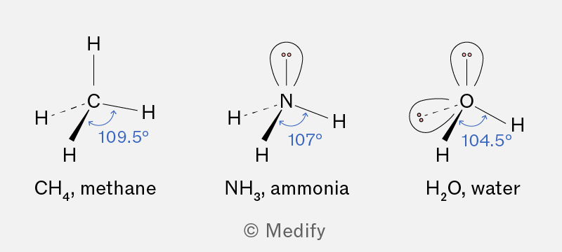
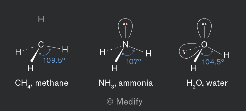
Replacing a bonding pair of electrons with a lone pair of electrons will decrease the bonding angle by 2.5°.
The geometries and bond angles of a series of covalent molecules, based on the number of bonding regions and lone pairs, can be seen in the table below.
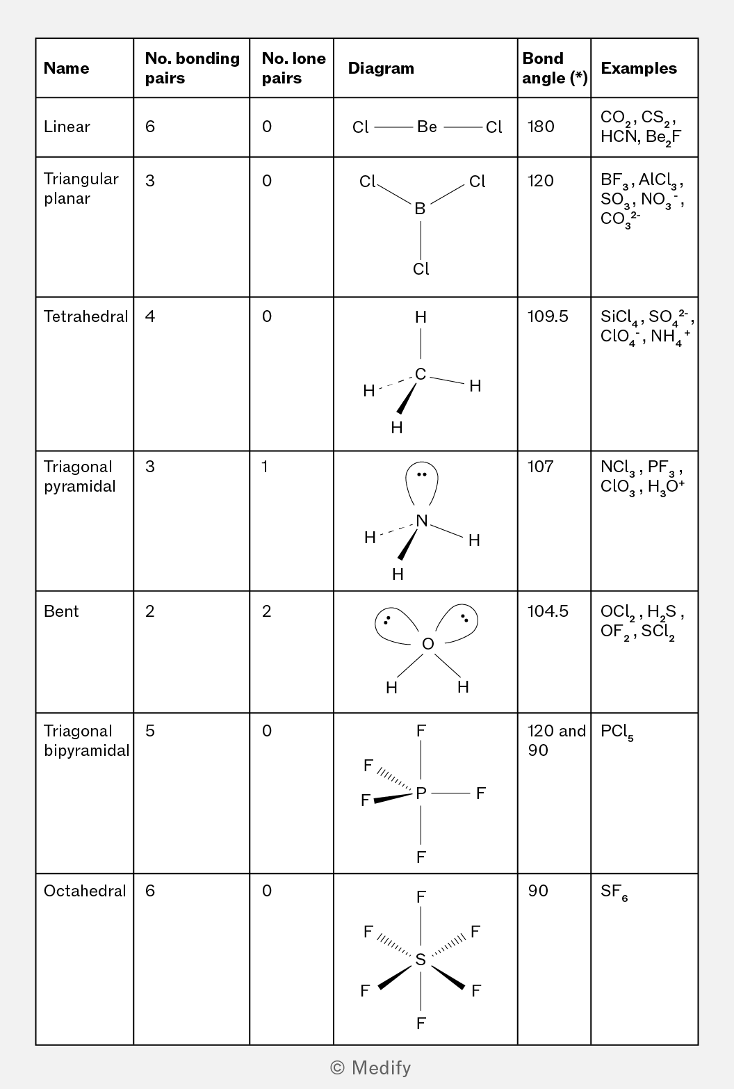
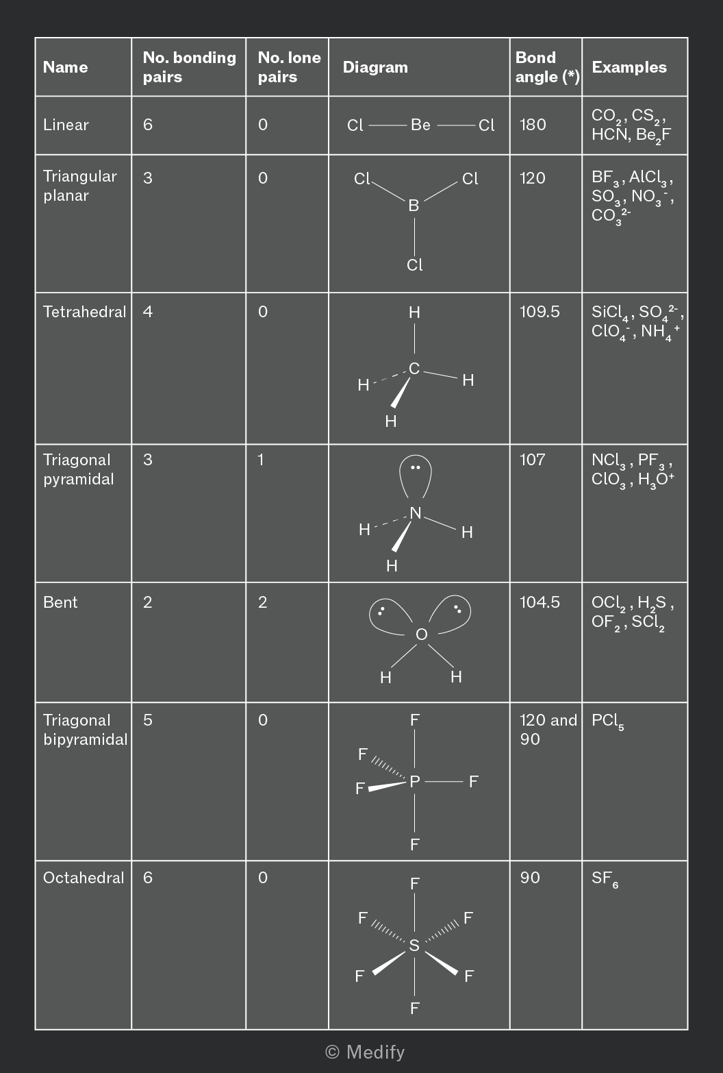
Molecular geometry and bond angles of
- Phosphorus is the central atom and is in Group 5, therefore there are five outer shell electrons.
- There are three covalent bonds to the phosphorus atom which means there are three bonding pairs. This means there is one lone pair .
Using the fact there are three bonding pairs and one lone pair we can deduce that the shape of is trigonal pyramidal with bond angles of 107°:
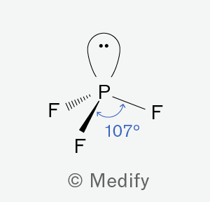
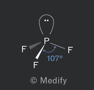
The shape is explained by electron pair repulsion theory. Electron dense regions (electron pairs) repel each other and arrange themselves as far apart as possible to minimise repulsion.
Note: lone pairs are positioned closer to the nucleus, and therefore produce a greater repulsive force than the bonded electrons. The bonding regions are pushed together, and the bond angle is slightly decreased compared to the tetrahedral angle of 109.5°.
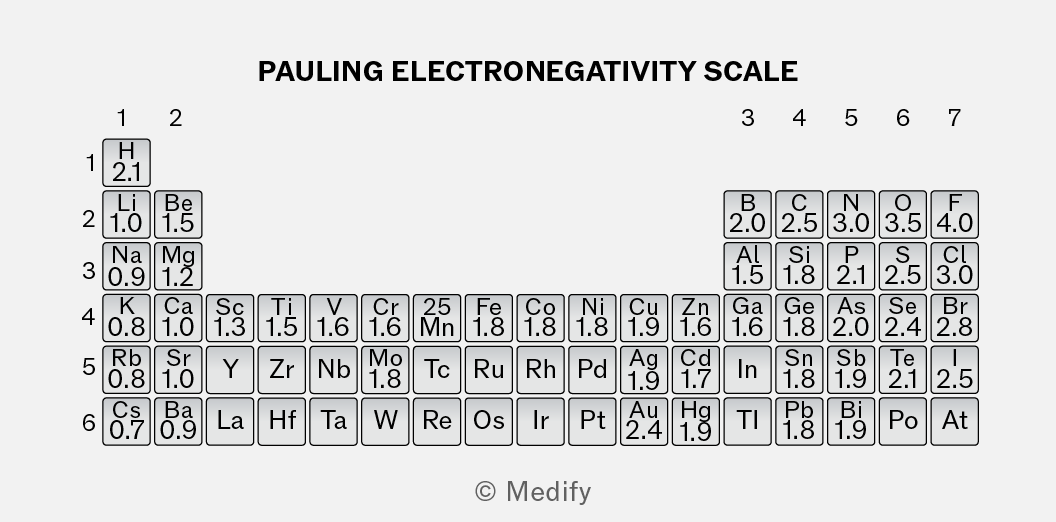
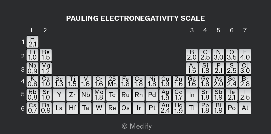
Electronegativity describes the ability of an atom to attract shared electrons in a covalent bond.
The Pauling scale is the most commonly used method to measure electronegativity.
It assigns a dimensionless number to each element based on experimental bond energies.
The key factors involved in assessing the electronegativity of an atom are:
- Atomic radius: Smaller atoms have higher electronegativity as the bonding electrons are closer to the nucleus and more strongly attracted.
- Shielding effect: More electron shells result in increased shielding, which reduces the effective nuclear charge felt by the bonding electrons, thus reducing electronegativity.
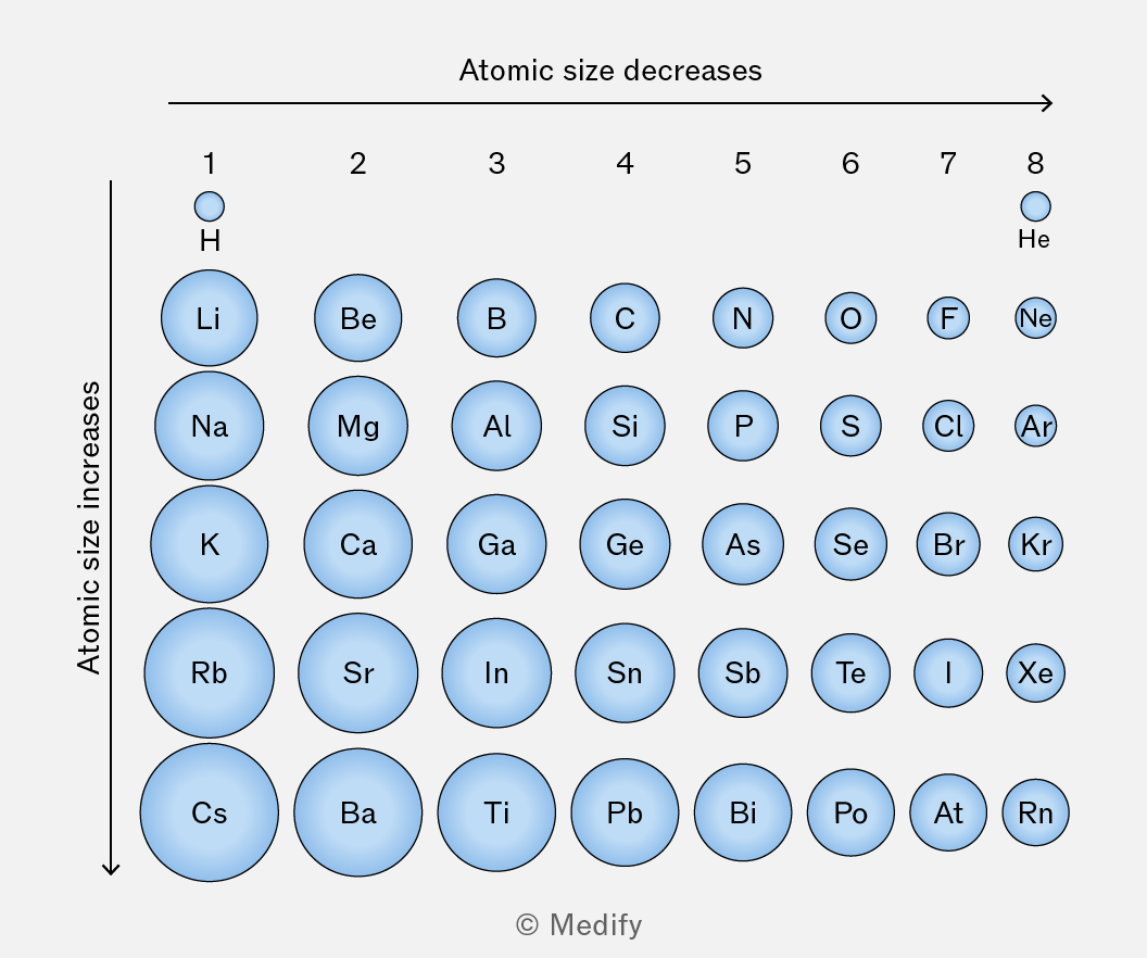
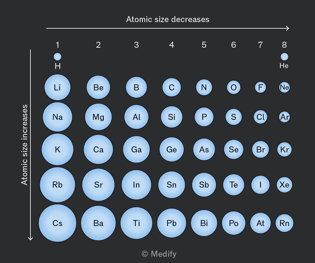
Electronegativity increases from left to right across a period due to increasing nuclear charge and decreasing atomic radius.
Electronegativity decreases down a group as the atomic radius increases and additional electron shells provide shielding which reduces the attraction between the nucleus and the bonding electrons.
A polar bond is a type of covalent bond where there is an unequal sharing of electrons between two atoms due to a difference in their electronegativities.
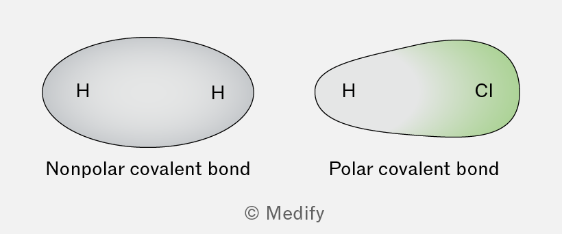
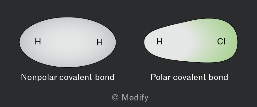
When two atoms with a difference in electronegativity form a covalent bond, the bonding electrons are attracted more strongly to the atom with higher electronegativity.
Partial charges describe the unequal sharing of electrons in a polar covalent bond. A partial negative charge forms on the more electronegative atom and a partial positive charge forms on the less electronegative atom.
A permanent dipole exists in a molecule if it has a polar bond.
It is represented by a dipole moment – a vector quantity with both magnitude and direction – pointing from the positive to the negative pole.
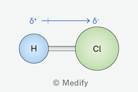
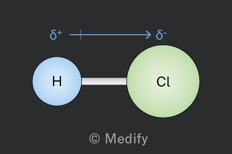
Chlorine has a higher electronegativity (3.0) compared to hydrogen (2.1).
The electrons are more attracted to , giving it a partial negative charge and a partial positive charge .
The dipole moment points from .
Molecular polarity exists when the polar bonds within a molecule create an overall molecular dipole.
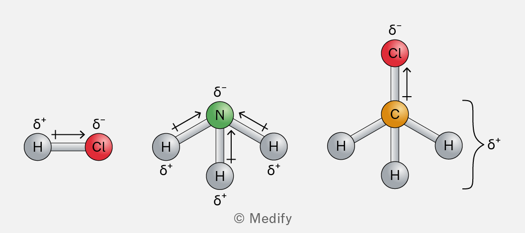
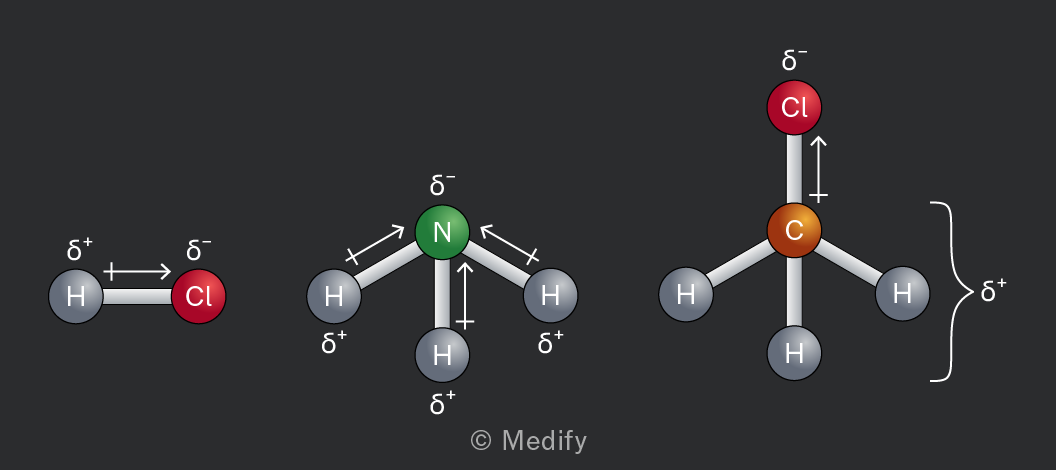
For a molecule to be polar, there must be a difference in the electron density on one side of the molecule from that of the other.
Polar bonds can be arranged in a way which does not create a positive and negative side to the molecule.
In the examples shown, you have a non-polar molecule containing polar bonds.
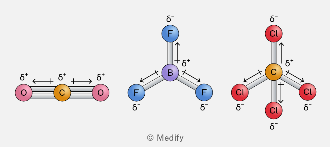
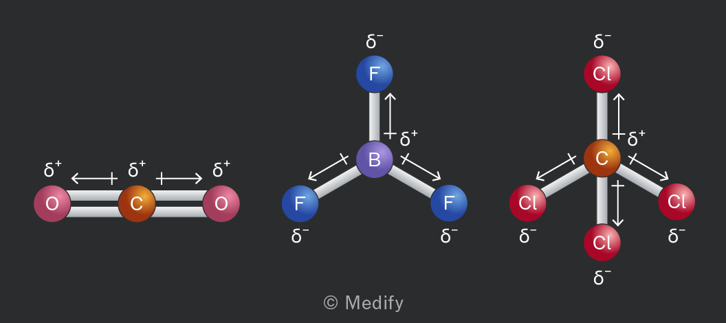
Dipole-dipole interactions and their associated physical properties are related to molecular polarity, not bond polarity.
Permanent dipole–dipole interactions occur in molecules that have a permanent dipole moment due to the difference in electronegativities between atoms in a covalent bond.
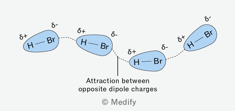
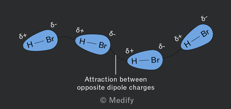
Induced dipole–dipole interactions, also known as London dispersion forces, occur between all molecules.
These forces arise when the electrons within a molecule momentarily shift to create a temporary dipole. This temporary dipole can induce a dipole in a neighbouring molecule, leading to a temporary attraction between the two.
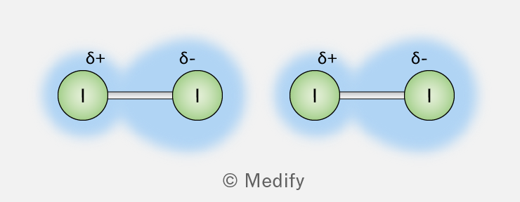
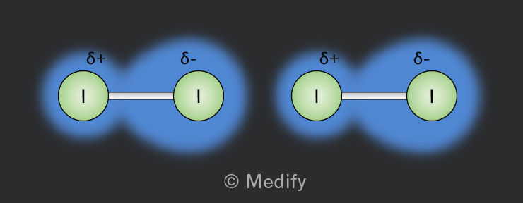
Van der Waals’ forces refer to intermolecular forces related to an uneven distribution of the electron cloud. This includes both induced dipole–dipole interactions (London forces) and permanent dipole–dipole interactions. DO NOT use the term Van der Waals’ in place of induced dipole-dipole interactions.
Hydrogen bonding is a special type of intermolecular force that occurs when hydrogen is bonded to highly electronegative atoms like nitrogen , oxygen , or fluorine .
Key criteria for hydrogen bonding
- Presence of hydrogen: Hydrogen must be directly bonded to .
- Lone pairs: The highly electronegative atom, , in the adjacent molecule must have accessible lone pairs of electrons.
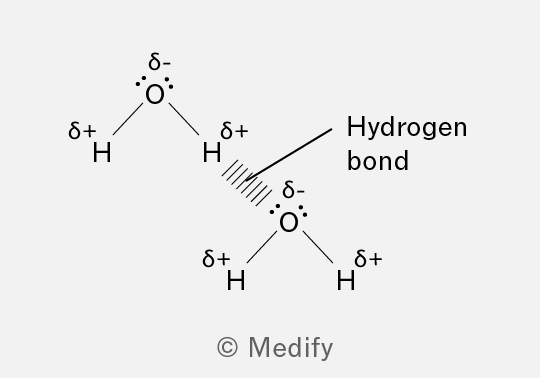
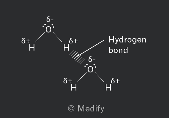
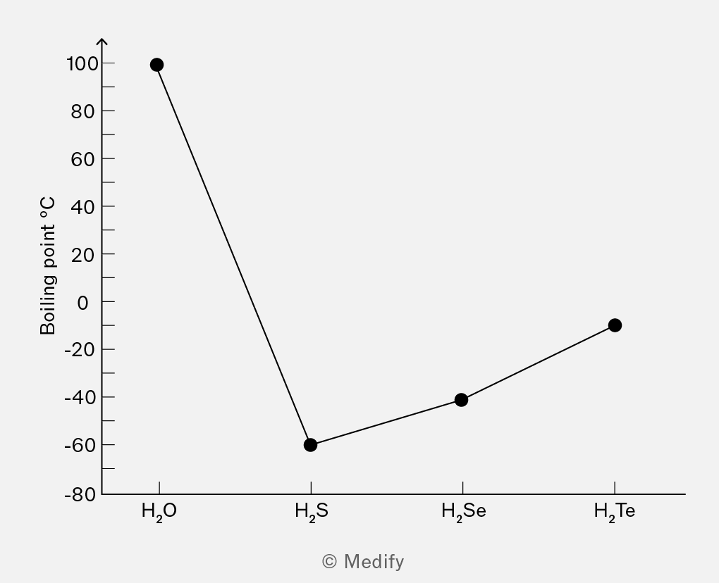
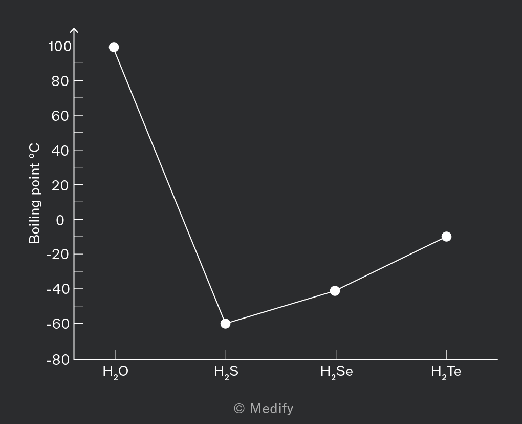
Water has unusually high melting and boiling points compared to other molecules of similar size, primarily due to hydrogen bonding. Hydrogen bonds are stronger than other types of dipole–dipole interactions due to the interaction between the hydrogen and the lone pair on the electronegative atom.
Melting point:
To transition from ice to liquid water, a significant amount of energy is required to break the hydrogen bonds holding the molecules in the crystalline lattice.
This energy requirement results in a higher melting point than would be expected for a molecule of water’s size.
Boiling point:
The boiling point of water is elevated because a considerable amount of energy is needed to overcome the hydrogen bonds between water molecules in the liquid state to turn them into vapour.
This makes water’s boiling point much higher than that of other hydrides like .
The primary forces holding simple molecules together in a lattice are intermolecular forces, which are much weaker than the covalent bonds within the molecules.
These forces can be categorised into three main types:
- London dispersion forces: Weak attractions due to temporary dipoles induced in atoms or molecules. Present in all molecules and directly linked to the size of the electron cloud.
- Dipole–dipole interactions: Occur between polar molecules where permanent dipoles attract each other.
- Hydrogen bonds: A stronger type of dipole–dipole interaction, where lone pairs formally associate in a weak bond. Occurring when hydrogen is bonded to highly electronegative atoms like nitrogen, oxygen, or fluorine, as seen in ice.
The relative strength of intermolecular forces is only directly comparable in similarly sized molecues. When the size of the molecule is the same:
London forces < dipole–dipole interactions < hydrogen bonding
Question walkthrough
Intermolecular forces
Linking molecular polarity to boiling point
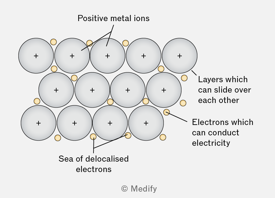
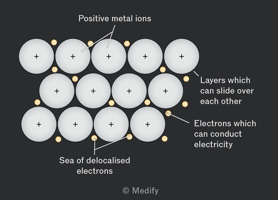
Metallic bonding arises from the electrostatic forces of attraction between positive metal ions and a sea of delocalised electrons.
The strength of metallic bonding increases across the period, from to , due to the following factors:
Charge of the ion
- Sodium forms , magnesium forms , and aluminium forms .
- Higher charge increases the attraction between the cation and anions in the lattice, strengthening the ionic bond.
Ionic radius
- The ionic radius decreases from to because of the increasing nuclear charge while the number of electron shells remains the same.
- A smaller ionic radius means a higher charge density, leading to stronger electrostatic attraction.
Charge density
- has the highest charge density (high charge and small size), is intermediate, and has the lowest charge density.
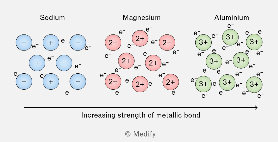
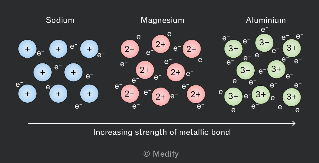
Thus, the strength of attraction between the cation and the surrounding electrons increases in the order: .
In a solid metal, each atom becomes a cation, donating its outer shell electrons to a ‘sea’ of delocalised electrons which are free to move throughout the whole structure.
The strong electrostatic forces of attraction between the cations and the delocalised electrons is metallic bonding.
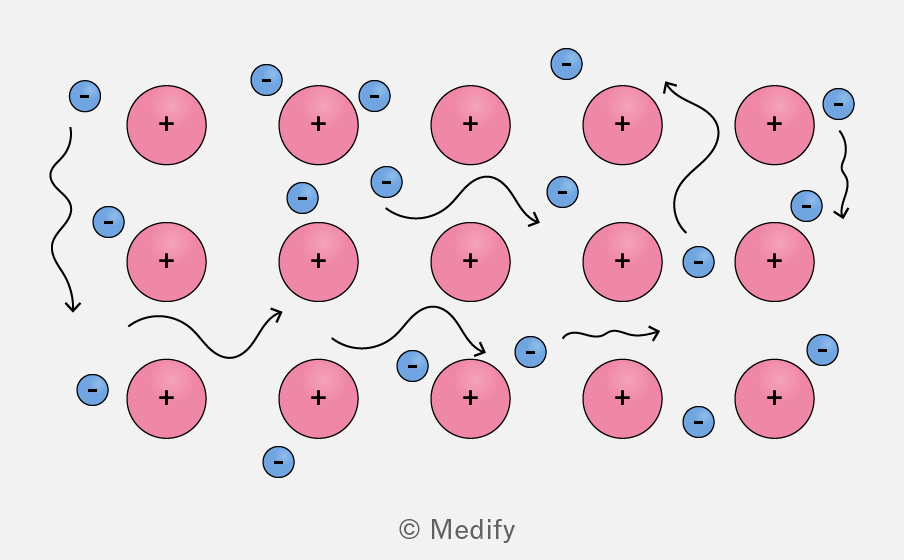
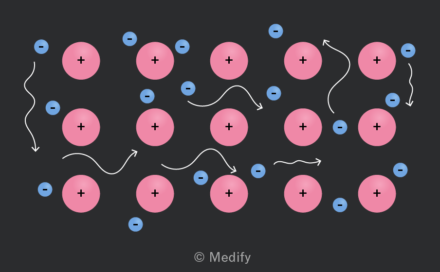
The cations are fixed in position; it is only the delocalised electrons which are free to move throughout the whole structure.
Where electrons are free to move there is electrical conductivity.
The bonding in magnesium is metallic bonding.
Lattice of positive ions: Magnesium atoms lose their two outermost electrons to form ions, which are arranged in a regular lattice structure.
Electrostatic attraction: Strong electrostatic forces exist between the positively charged ions and the delocalised electrons, holding the structure together.
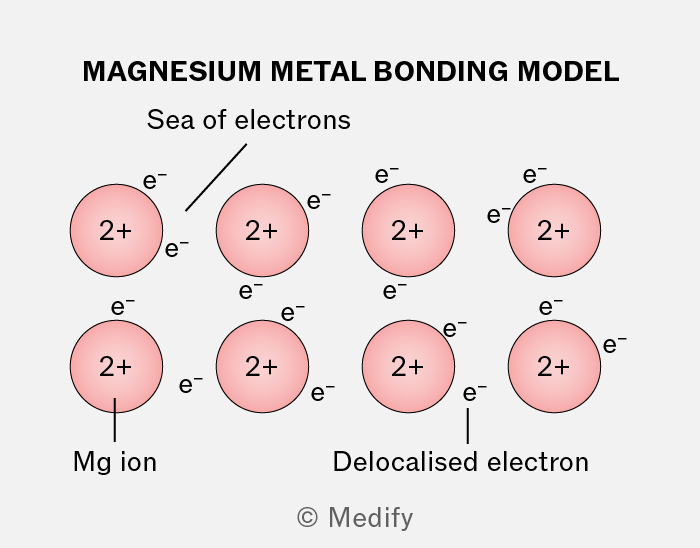
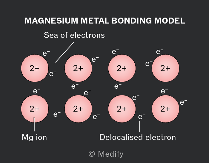
Delocalised electrons: The lost electrons become free-moving (delocalised) within the metallic lattice, creating a ‘sea of electrons’.