Module 1: Development of practical skills in physics›Essential practical techniques in physics (1.2.2)

Metre ruler

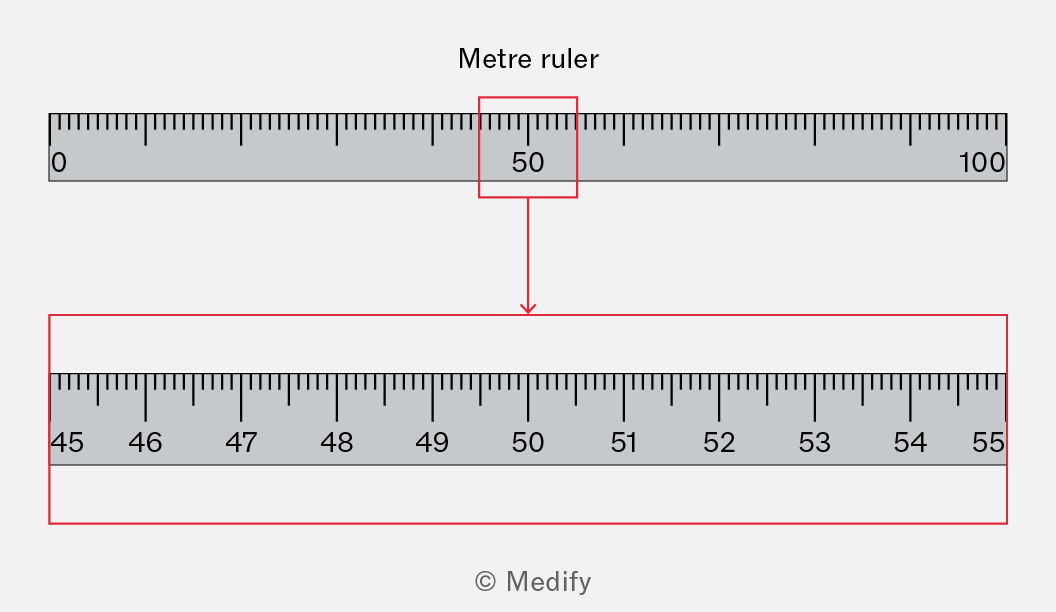
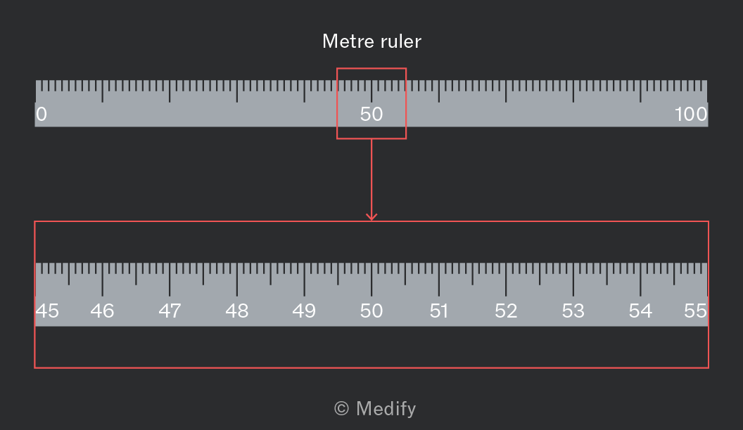
The image shows a 'Metre ruler' at the top with a scale ranging from 0 to 100. Below, a red box highlights the midpoint at 50, with a red arrow pointing downward to a magnified view of the ruler. The magnified section shows the scale from 45 to 55, with each unit clearly marked. The magnification emphasizes detail between these numbers.

A metre ruler or half-metre ruler is the standard analogue apparatus for measuring lengths from a few millimetres up to Graduations are typically every giving a resolution of on a single reading and on a difference of two readings. The eye must be positioned directly above the scale to avoid parallax error.

Add to favourites

Vernier callipers

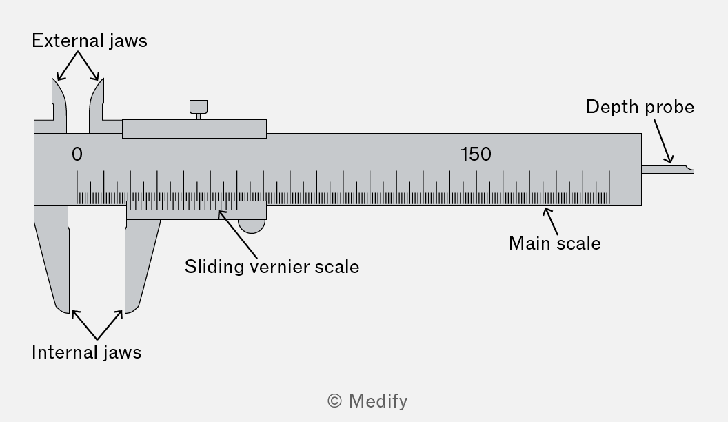
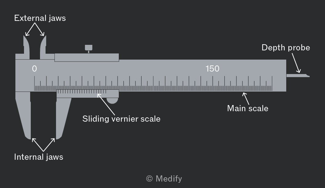
Image of a vernier caliper with labeled parts. The caliper has external jaws at the top and internal jaws at the bottom, both labeled. The main scale is marked with numbers, starting from 0 on the left and 150 on the right, with smaller incremental markings in between. The sliding vernier scale is positioned below the main scale and is labeled. A depth probe extends from the right end, also labeled. The caliper has a thumb screw at the top for adjusting the sliding vernier scale.

Vernier callipers measure small lengths (typically up to ) to a resolution of (analogue) or (digital). They have external jaws for outer dimensions, internal jaws for inner dimensions, and a depth probe for hole or step depths.

Always check for zero error with the jaws closed. Record any offset and subtract it from each reading. The reading is taken as:

main scale + vernier scale × resolution

Tighten the jaws gently against the object: over-tightening compresses soft samples and gives a systematic underestimate.

Add to favourites

Protractor

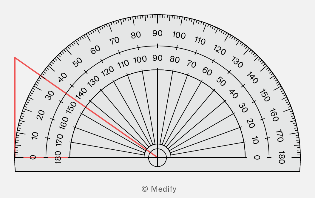
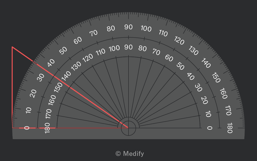
A protractor with a semicircular shape displaying angle measurements from 0 to 180 degrees. The outer edge shows degrees in increments of 10, from 0 on the far left to 180 on the far right. A red angle is highlighted, originating from the center of the protractor and extending to the 150-degree mark on the outer edge, forming a right triangle with the horizontal baseline. The protractor is labeled © Medify at the bottom center.

A protractor is the standard analogue apparatus for measuring angles. Standard semicircular protractors read with a resolution of

Align the centre cross-hair on the vertex and one light ray on the line, then read the angle off the scale. When measuring angles of refraction or diffraction, increase precision by drawing the ray as long as possible and taking the angle from a line through several points, not just two.

Add to favourites

Newton meter

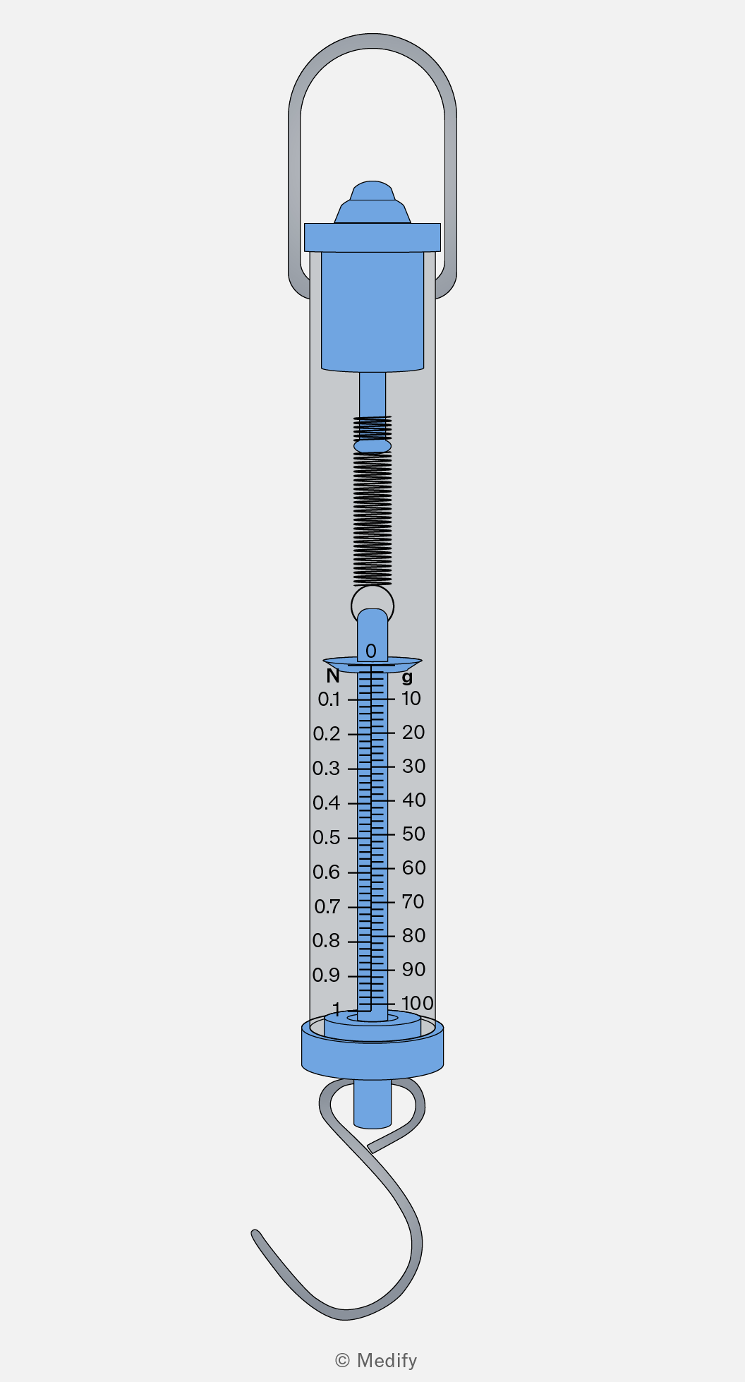
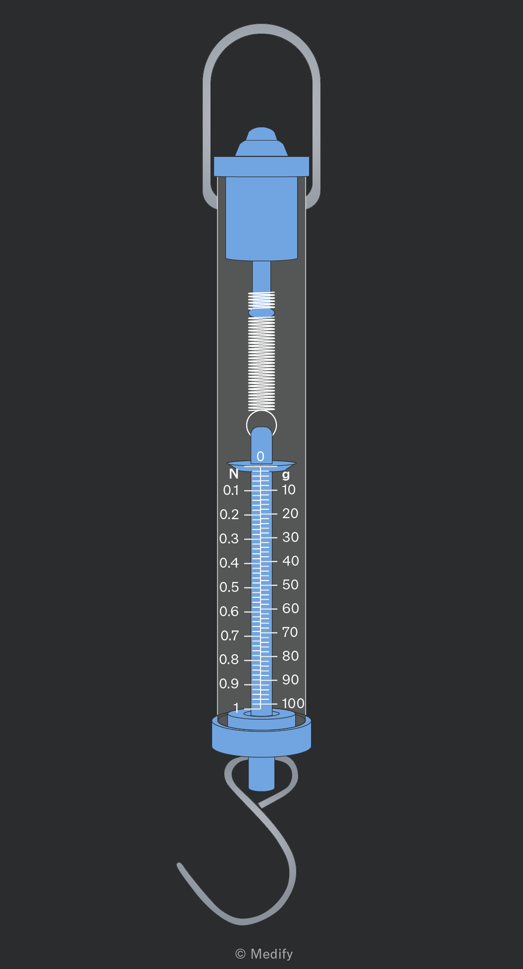
The image shows a blue and gray spring scale with a metal hook at the bottom. The scale has a central cylinder with a spring inside and a plunger marked with '0' at the top. The scale is marked on the left side with 'N' and values from 0 to 1 in increments of 0.1, and on the right side with 'g' and values from 0 to 100 in increments of 10. The scale is encased in a transparent outer casing with a loop at the top for hanging.

A Newton meter (spring balance) is an analogue device for measuring force directly in newtons. It uses an internal spring obeying Hooke’s law; extension is proportional to applied force. In school settings, Newton meters are typically available in ranges such as

Choose a range where the expected force sits near the middle of the scale to minimise fractional uncertainty. Always check for zero error with no load on the hook. Read at eye level to avoid parallax. Newton meters measure weight directly. To obtain mass, divide by the local value of

Add to favourites

Ticker timer

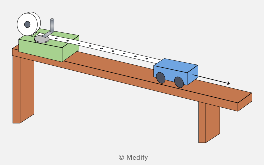
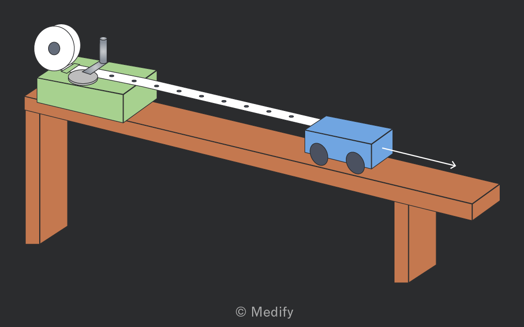
The image depicts a setup on a wooden table with a green box on the left and a blue cart on the right. A strip of tape is unwinding from a roll on top of the green box, passing over a wheel, and extending to the blue cart. The tape has evenly spaced holes. An arrow is drawn from the blue cart, indicating a direction towards the right. The setup appears to be a demonstration of motion or force. The image is labeled with copyright © Medify.

A ticker timer is a mains-driven oscillating hammer that marks dots on a paper tape at (in the UK; matched to mains electricity), i.e. one dot every By attaching the tape to a moving object, distance–time information is captured, and velocity and acceleration can be deduced from gap spacing along the tape.

Count gaps, not dots, when working out time: For acceleration, measure two velocities at different points along the tape and use:

Friction between the tape and timer is a systematic error. This is a measurement method that requires minimal technology. Light gates or a data logger are preferable for high-precision work.

Add to favourites

Liquid-in-glass thermometer

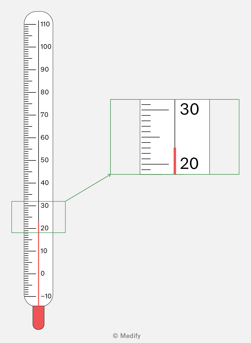
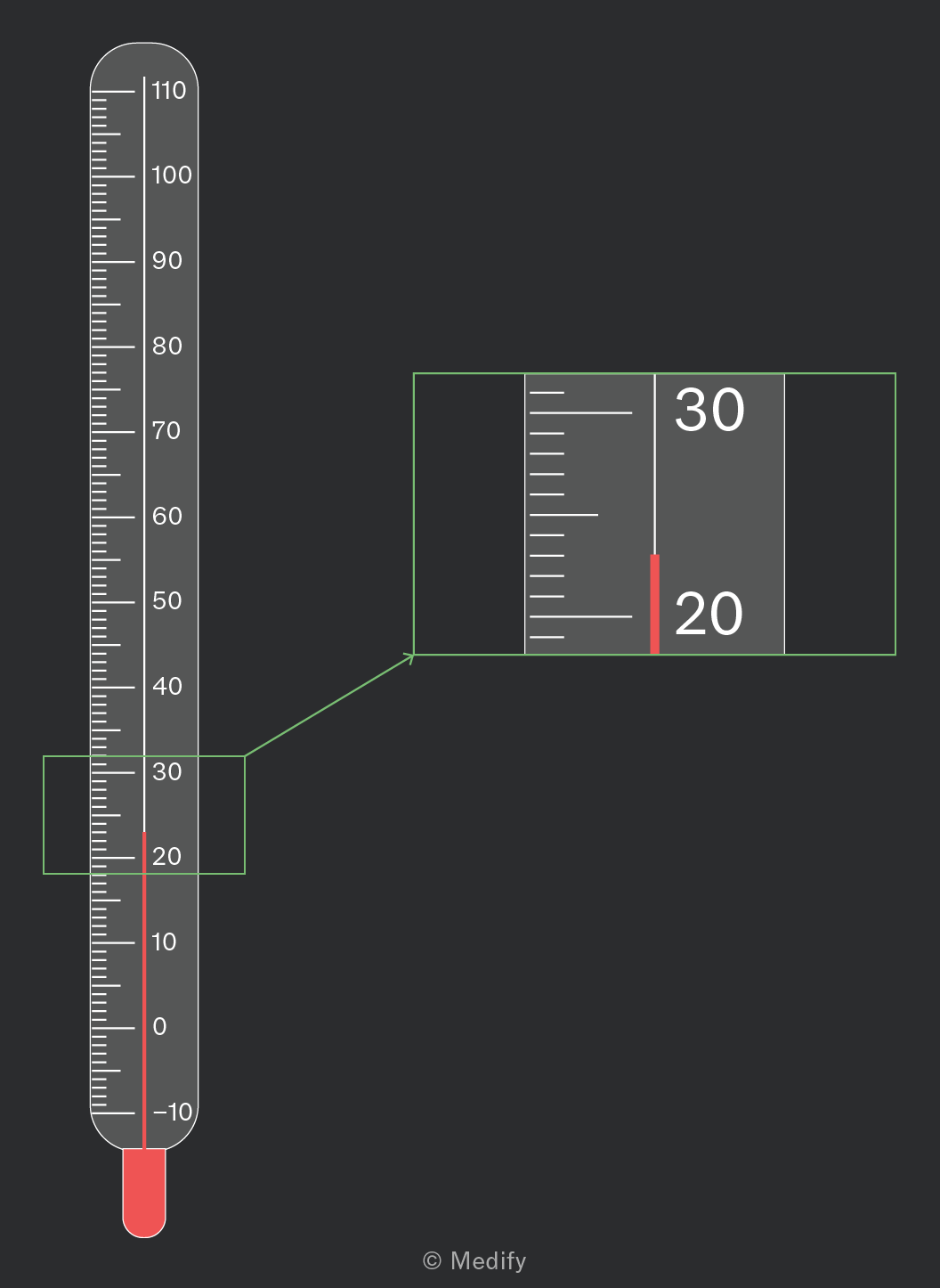
An image of a thermometer with a magnified section. The thermometer has a scale ranging from -10 to 110 degrees, marked at intervals of 10. The mercury level is approximately at 23 degrees. The magnified section highlights the region between 20 and 30 degrees, with a red line at approximately 23 degrees. The numbers 20 and 30 are clearly labeled in the magnified section.

A liquid-in-glass thermometer is an analogue apparatus for measuring temperature. A reservoir of coloured spirit (or, in older instruments, mercury) at the bulb expands and rises up a narrow capillary against a calibrated scale. Typical school thermometers cover to with graduations.

Immerse the bulb fully and wait until the level stops rising before reading. Take the reading at eye level, at the top of the liquid column, to avoid parallax error. For Boyle’s law or specific heat capacity experiments, allow time for thermal equilibrium between the thermometer and the sample.

Add to favourites

Analogue ammeter

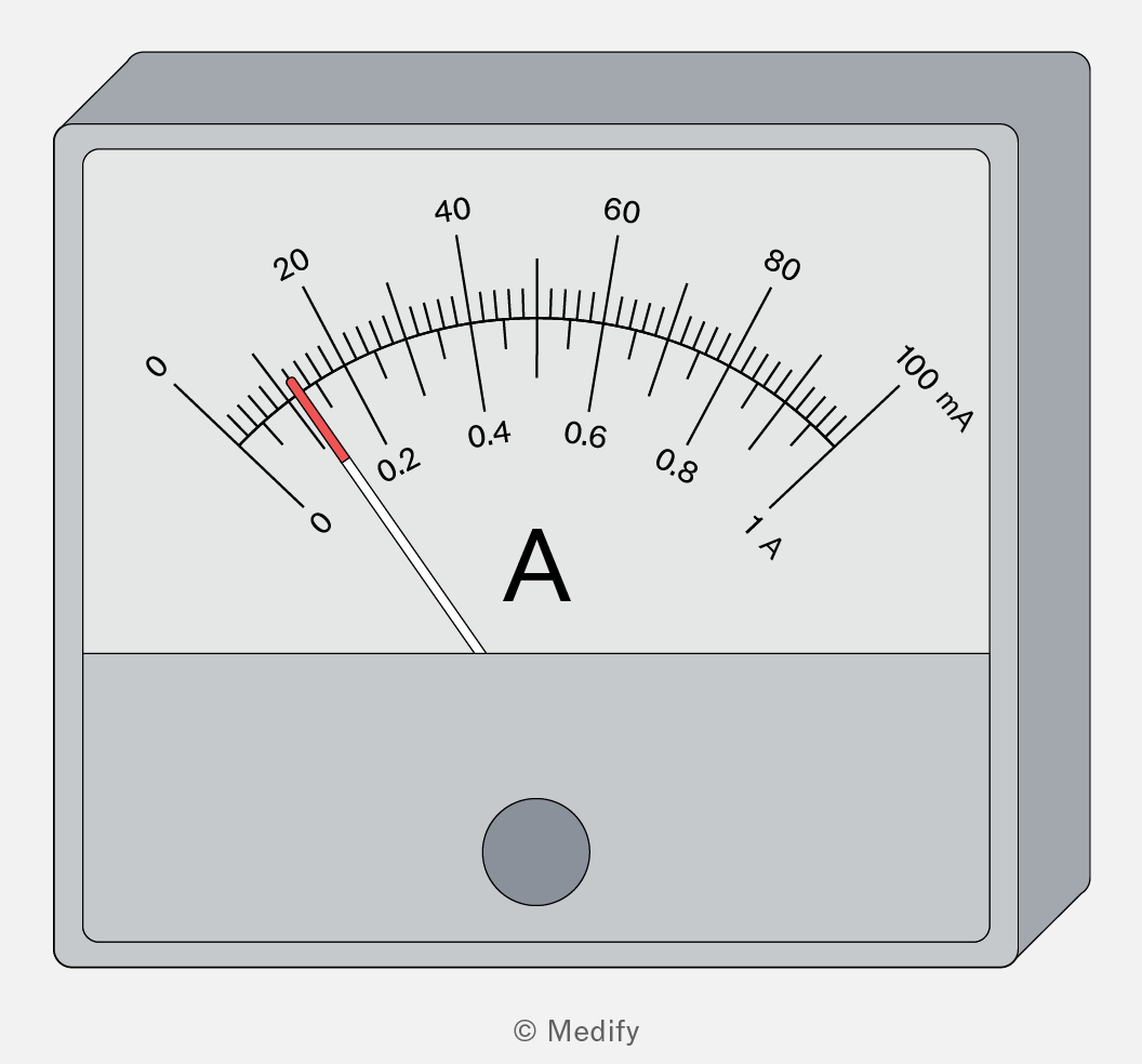
An analog ammeter with a needle pointing to approximately 0.18 on the scale. The scale is marked from 0 to 100 mA on the outer arc and from 0 to 1 A on the inner arc. The scale includes major ticks labeled 0, 20, 40, 60, 80, and 100 mA, and corresponding values 0, 0.2, 0.4, 0.6, 0.8, and 1 A. The center of the meter displays a large 'A' indicating amperes. The needle is red and white, positioned slightly below the 0.2 A mark. The ammeter has a grey casing and a circular knob below the display.

An analogue ammeter measures electric current in a circuit using a moving-coil galvanometer with a calibrated scale. It is always connected in series with the component carrying the current. Typical school models offer ranges such as and on dual scales.

Choose a range where the expected current sits in the upper half of the scale to reduce fractional uncertainty. Read at eye level to avoid parallax.

Add to favourites

Analogue voltmeter

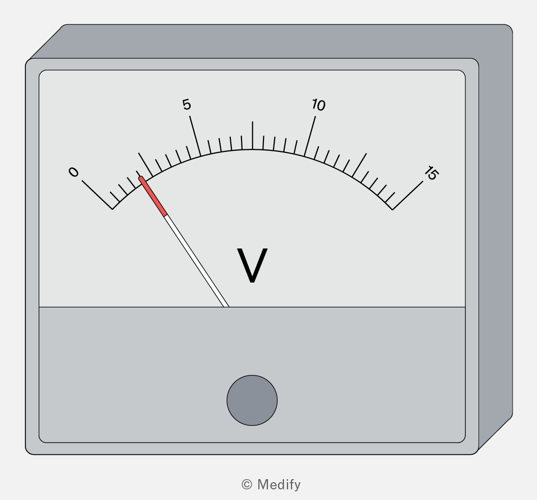
An analog voltmeter displaying a scale from 0 to 15 volts. The scale is marked with intervals at every 1 unit, with larger marks and numbers at 0, 5, 10, and 15. The needle points slightly above the 0 mark. The center of the display has a large letter 'V' indicating volts. The meter has a gray casing with a circular knob or button below the display.

An analogue voltmeter measures the potential difference (p.d.) across a component. It is connected in parallel with the component. School models commonly offer and ranges via a dual scale.

Choose a range where the expected p.d. sits near the upper end of the scale to minimise fractional uncertainty. A voltmeter has very high resistance, so adding it to a circuit branch should not significantly change the current.

Add to favourites

Top pan balance

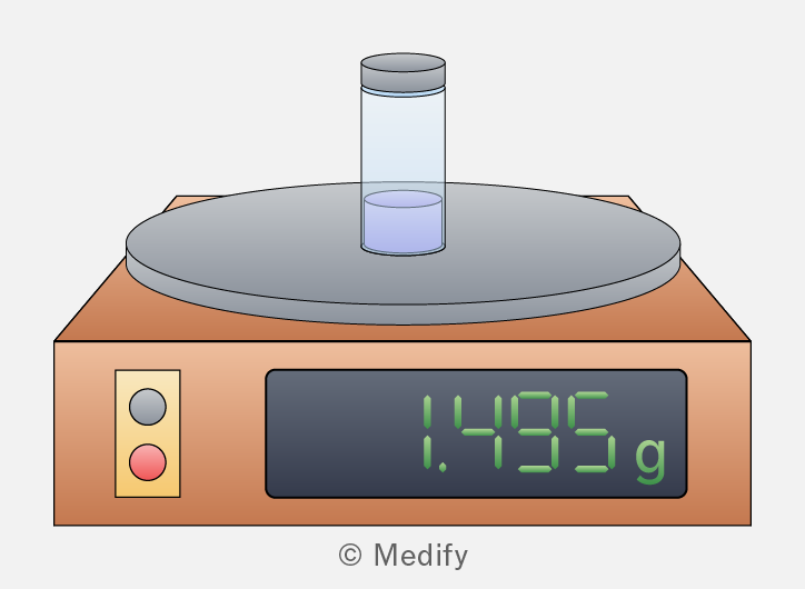
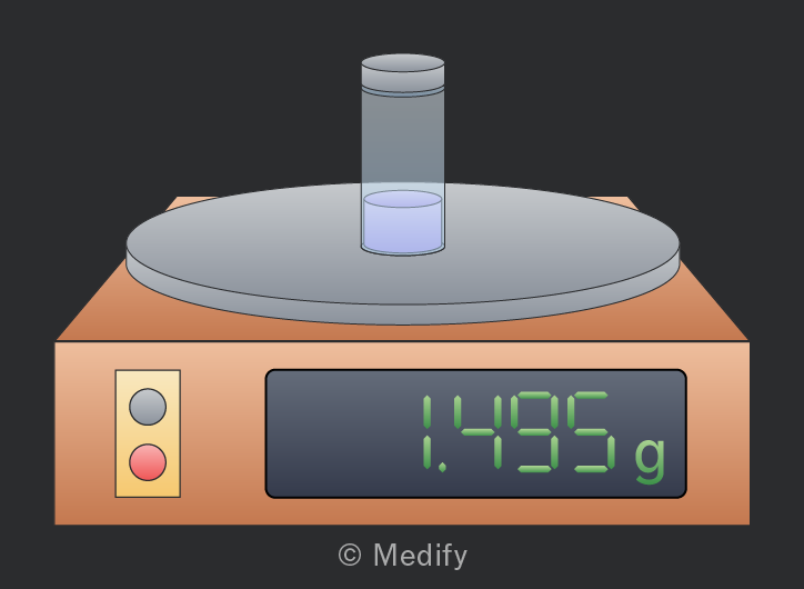
A digital scale displaying a weight of 1.495 grams with a small glass container filled with liquid placed on the weighing platform.

Top pan balances are less accurate than analytical balances but can be used for heavier samples. Their accuracy generally ranges from 1 to 3 decimal places.

The lack of draft exclusion makes weighing on a top pan balance more rapid.

Add to favourites

Digital thermometer

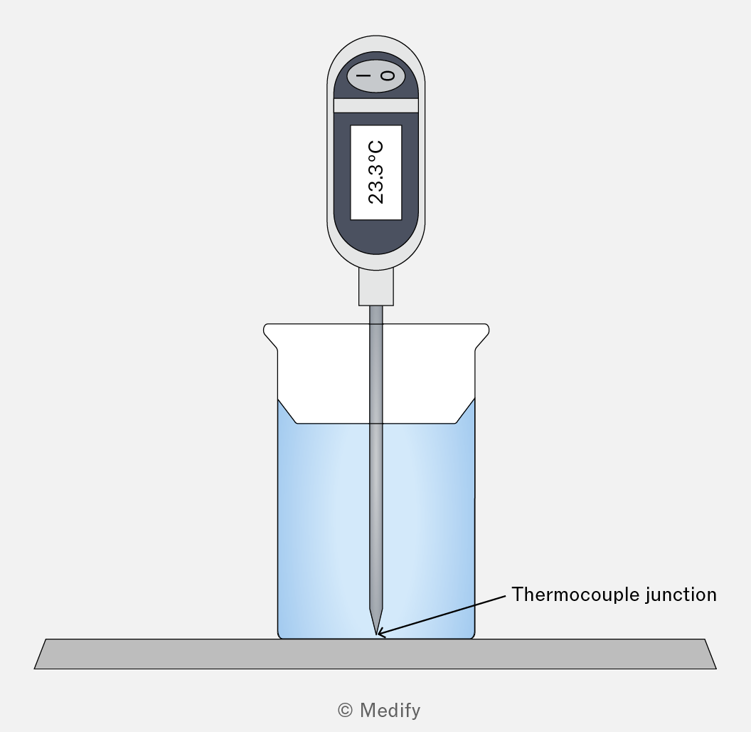
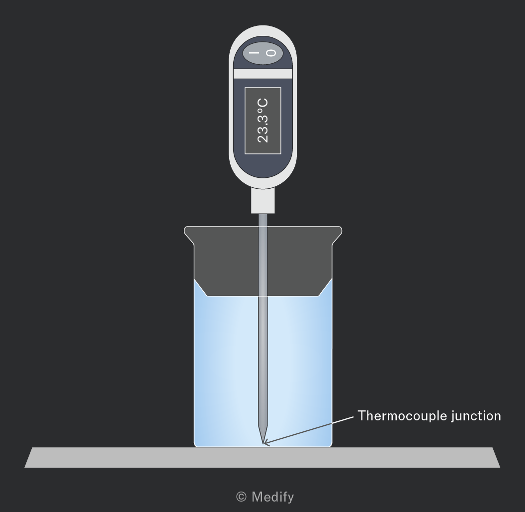
The image shows a digital thermometer inserted into a beaker containing a blue liquid. The thermometer displays a temperature of 23.3°C. A label points to the bottom of the thermometer, indicating the 'Thermocouple junction.' The thermometer is vertically positioned above the beaker, with the probe submerged in the liquid. The beaker is placed on a flat surface. The image is labeled © Medify.

Digital thermometers use a thermistor or thermocouple probe and display temperature on a liquid crystal display (LCD), typically to a precision of Thermocouples (a junction of two dissimilar metals generating a small electromotive force) can be used at much higher temperatures than liquid-in-glass thermometers, often above

Digital probes have low thermal mass and respond quickly, making them ideal for cooling curves and transient temperature changes. The probe must be fully immersed in the medium and not touching the container wall. As with all digital instruments, the displayed resolution sets the uncertainty of a single reading.

Add to favourites

Digital multimeter

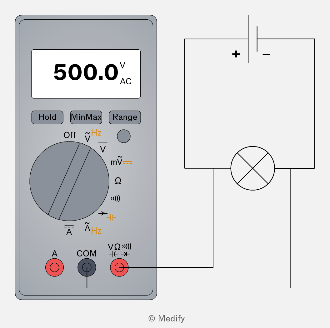
The image shows a digital multimeter with a display reading '500.0 V AC'. The multimeter has several buttons labeled 'Hold', 'MinMax', and 'Range'. A large dial on the multimeter shows various settings, including Off, V for voltage, mV, Ohm for resistance, and Hz for frequency. There are three ports labeled 'A', 'COM', and 'V(Ω)'. Wires from the 'COM' and 'V(Ω)' ports connect to a circuit diagram on the right, featuring a battery symbol with '+' and '-' signs and a circular symbol representing a light bulb.

A digital multimeter (DMM) is a single digital instrument that can be set to measure current, voltage, resistance and (on most models) capacitance. It is the workhorse of A-level electrical practicals: it is used in resistivity, electromotive force/internal resistance and potential-divider experiments.

Always connect the voltmeter setting in parallel and the ammeter setting in series.

Add to favourites

Hall probe

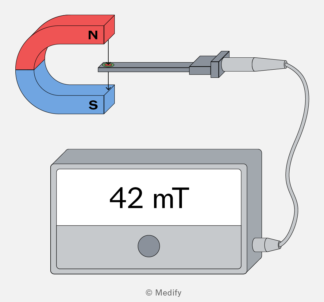
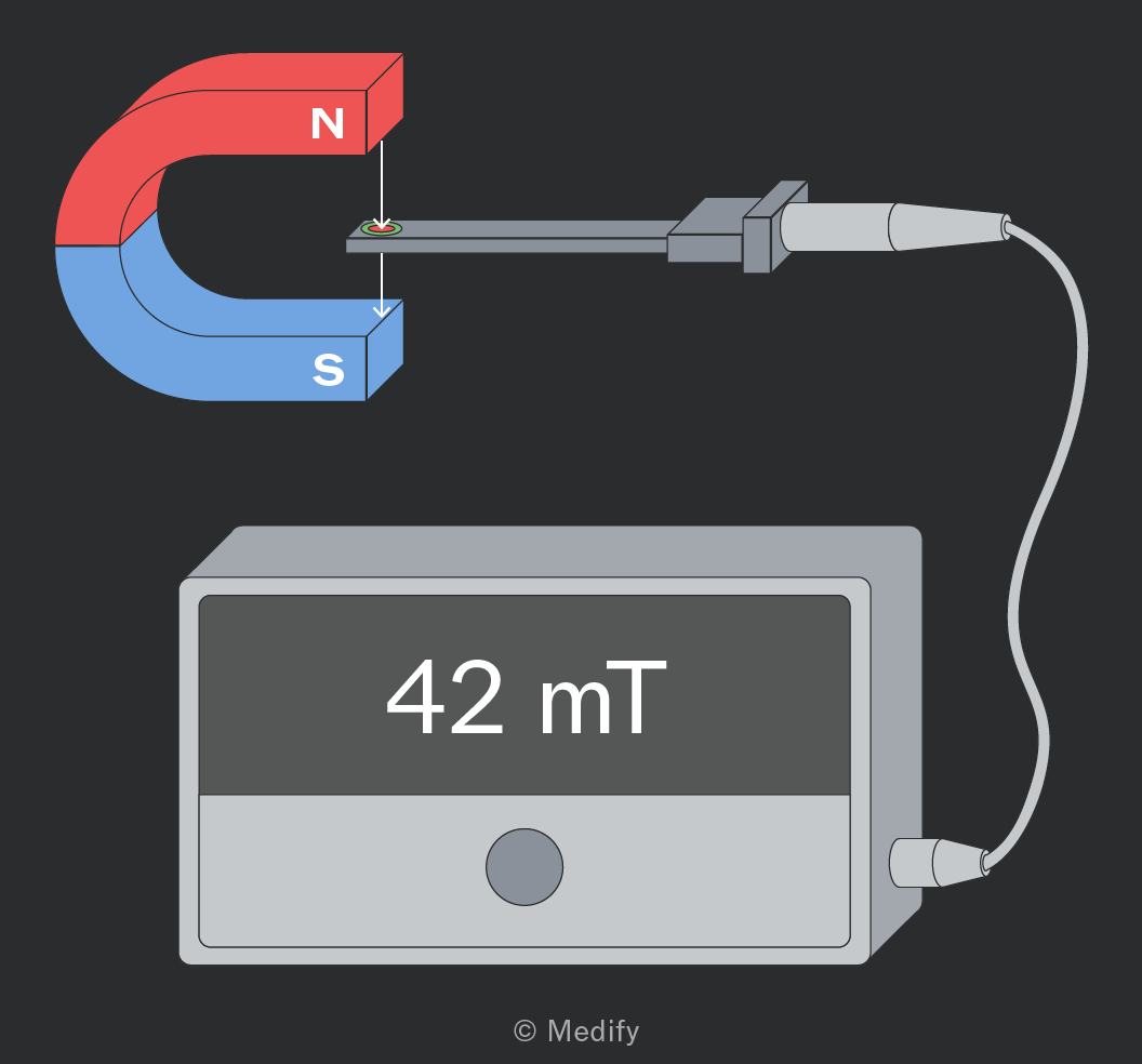
The image shows a horseshoe magnet with the north pole labeled 'N' in red and the south pole labeled 'S' in blue. A probe is positioned between the poles, connected to a device via a cable. The device displays '42 mT' in large black text on its screen. The setup appears to measure the magnetic field strength between the magnet's poles.

A Hall probe is a small digital instrument for measuring magnetic flux density, directly. A thin semiconductor wafer at the tip carries a known current; in a magnetic field, charge carriers are deflected sideways, producing a transverse Hall voltage that is proportional to and displayed in or on the meter.

The flat face of the sensor must be held perpendicular to the field for the maximum reading: tilting the probe gives a reduction. Zero the meter in a field-free region before each set of readings. Unlike a search coil, the Hall probe works in steady (DC) fields, so it is the natural choice for mapping the field of a bar magnet or determining inside a current-carrying solenoid.

Add to favourites

Calorimeter

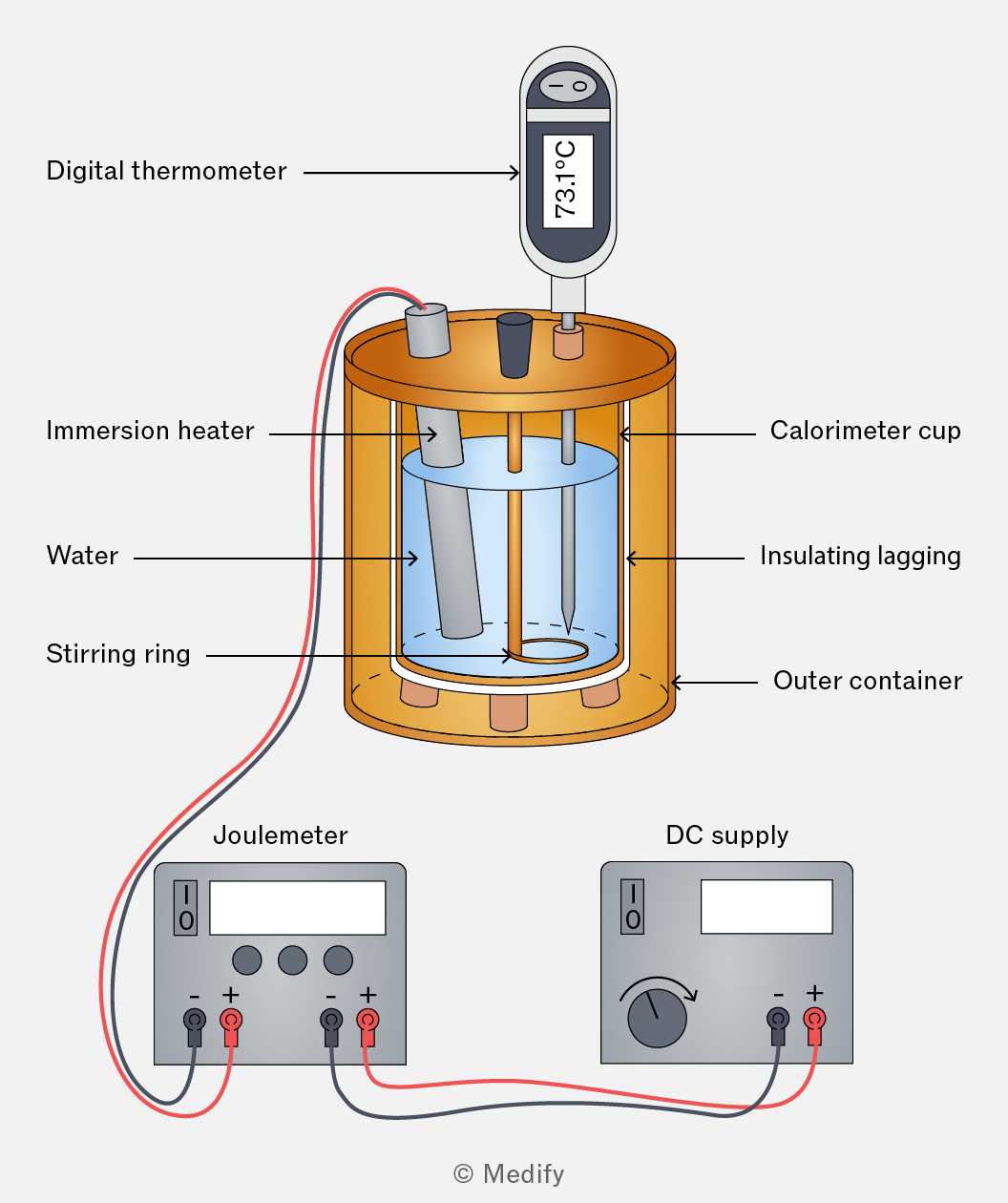
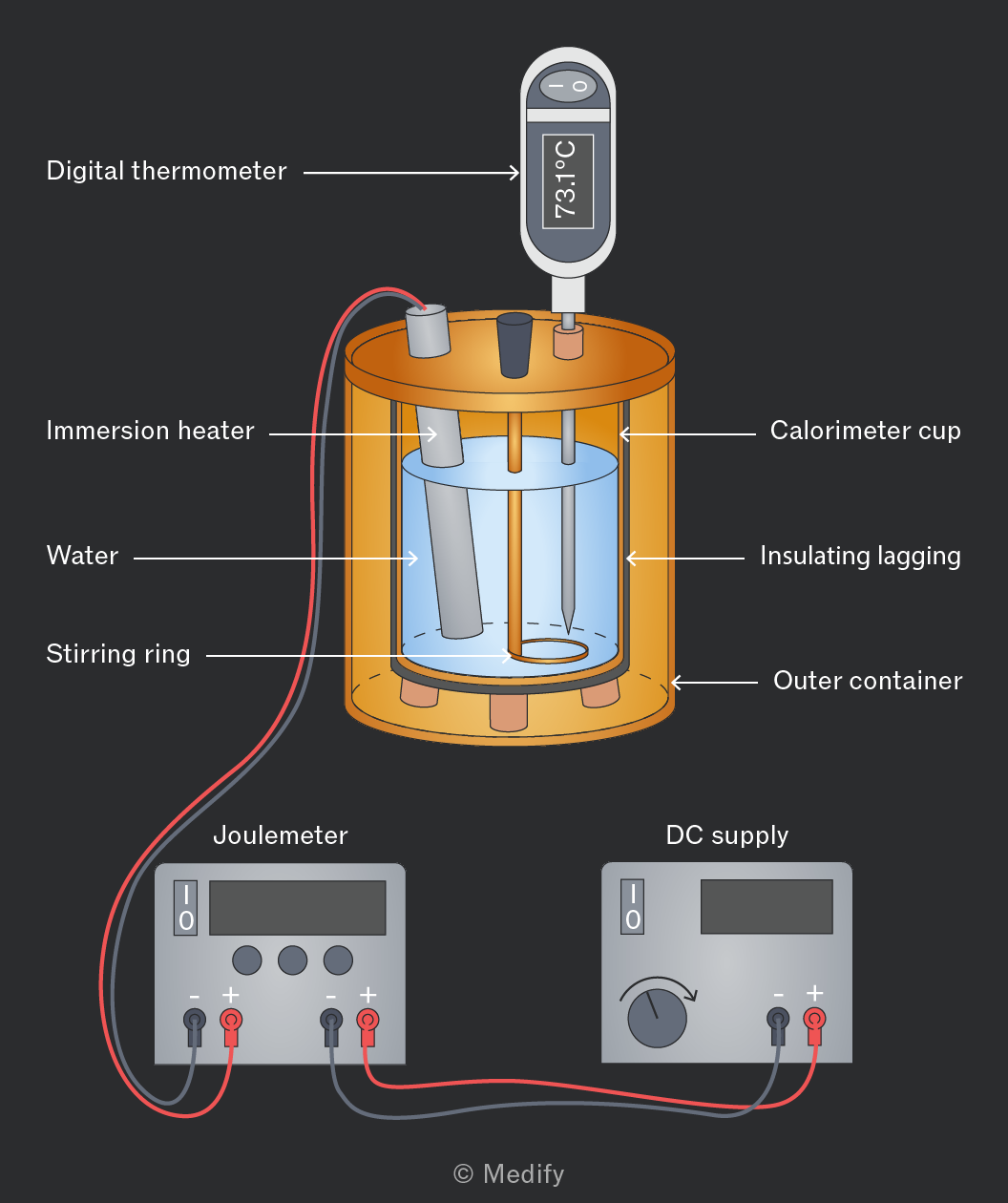
The image shows a calorimeter setup with labeled components. At the top, a digital thermometer reads 73.1°C. The calorimeter cup is surrounded by insulating lagging and placed inside an outer container. Inside the cup, there is an immersion heater, water, and a stirring ring. Cables connect the immersion heater to a joulemeter and a DC supply. The joulemeter and DC supply are located below the calorimeter, with cables visibly connecting them to the heater.

A calorimeter is a thermally insulated vessel, typically a copper cup wrapped in lagging, or an expanded-polystyrene cup. It is used to contain a substance whose specific heat capacity, or specific latent heat, is being determined. The lagging minimises heat loss to the surroundings during the measurement.

Add to favourites

Set square

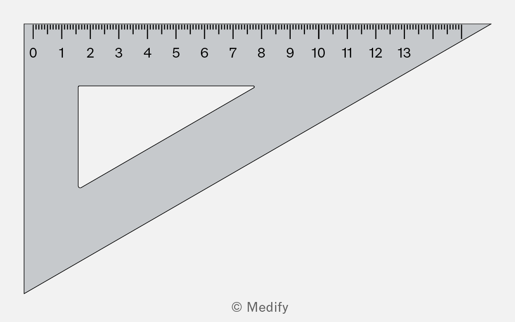
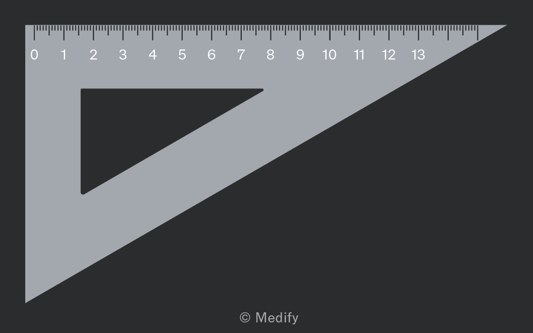
Image of a triangular ruler with a right angle. The hypotenuse of the triangle has a ruler scale marked from 0 to 13 with individual millimeter markings. The scale is labeled with numbers at each centimeter: 0, 1, 2, 3, 4, 5, 6, 7, 8, 9, 10, 11, 12, 13. Inside the triangle, there is a smaller triangular cutout. The image has a copyright notice at the bottom with the text '© Medify'.

A set square is a rigid triangular ruler used to increase the accuracy of a length measurement by enforcing a perpendicular alignment. The two triangle types most frequently encountered are those with angles measuring and those with angles of

A set square is used to read a ruler at eye level, perpendicular to the scale, removing parallax error. It also ensures a ruler is held vertically (e.g. when timing a free-falling object, or measuring the amplitude of an oscillation), and that the normal drawn for refraction experiments is genuinely at to the boundary.

Add to favourites

Plumb line

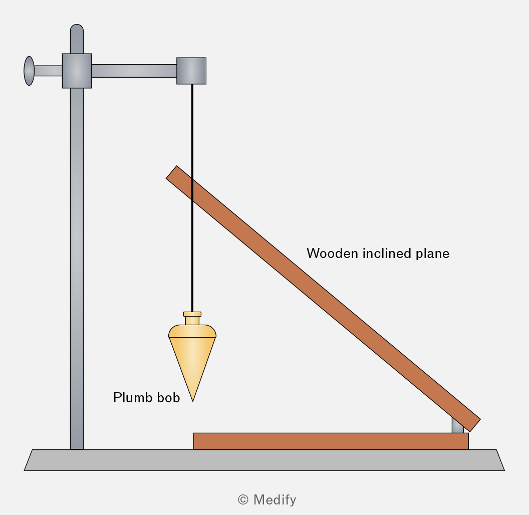
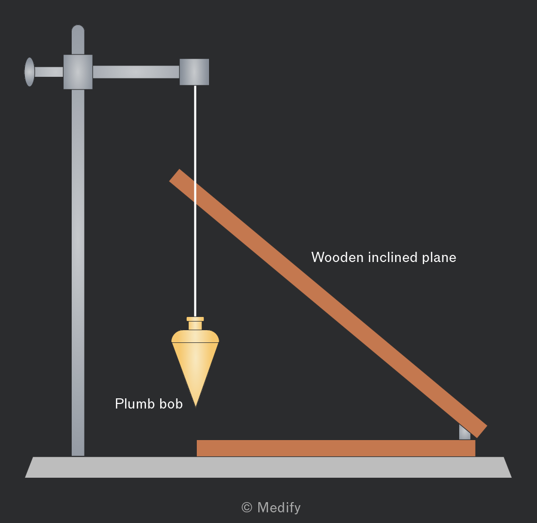
The image depicts a wooden inclined plane setup. A wooden inclined plane is positioned on a horizontal base, with its higher end supported by a vertical stand. A plumb bob is suspended from the top of the stand, with the string hanging vertically downwards, crossing the inclined plane. The text labels in the image indicate 'Wooden inclined plane' along the plane and 'Plumb bob' near the plumb bob.

A plumb line is a small dense mass (the plumb bob) suspended from a thin string. Gravity defines the string as truly vertical once the bob is at rest. It is used to increase the accuracy of length and angle measurements by providing a reliable vertical reference.

It is useful when the workbench is not level. For example, when setting up a free-fall apparatus so the release point is directly above the landing point, or when checking that a retort stand and ruler are vertical for a pendulum experiment. The bob must be allowed to come to rest before any reading is taken.

Add to favourites

Fiducial marker

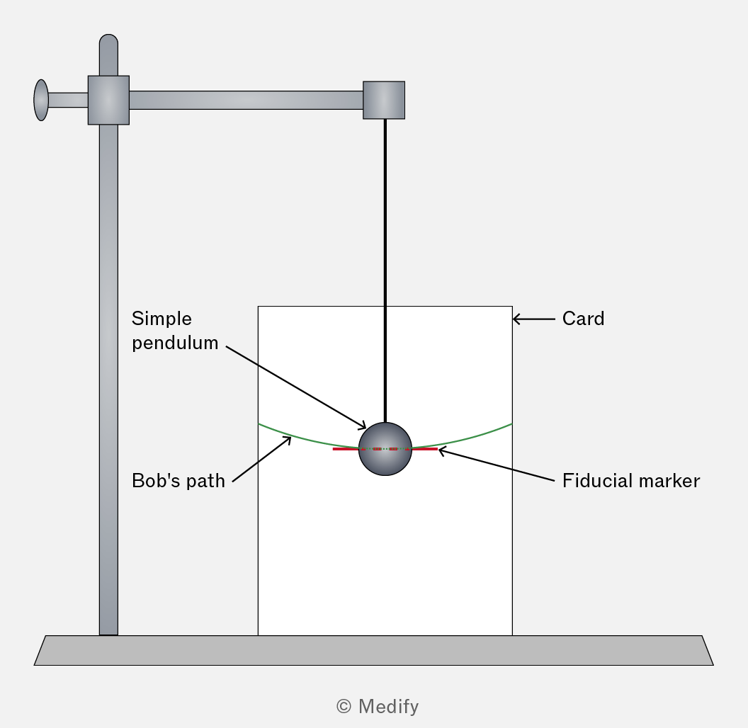
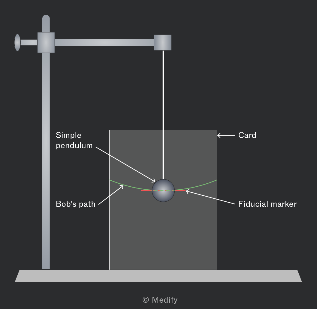
The image depicts a simple pendulum setup. A vertical stand supports a pendulum consisting of a string and a bob. The pendulum's bob is shown in the middle of its swing path, marked by a green curved line labeled 'Bob's path.' The bob is also aligned with a red dashed line labeled 'Fiducial marker.' A card is positioned behind the pendulum, labeled 'Card.' Annotations include 'Simple pendulum' pointing to the pendulum setup. The image is credited to © Medify.

A fiducial marker is a fixed reference point (e.g. a pin, line on a card, or notch on a stand) placed at the equilibrium position of an oscillating object. It defines a precise moment at which to start and stop the stopwatch when timing a period.

Add to favourites

Stop-clock

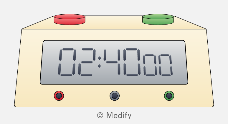
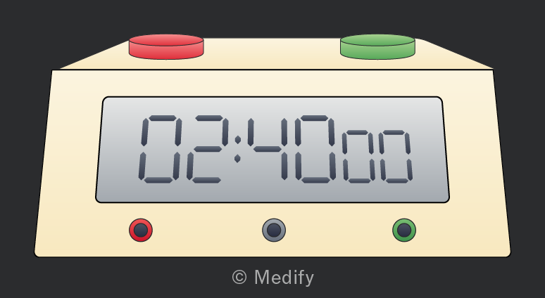
A digital timer displaying 02:40:00, with a red button on the left, a green button on the right, and a black button below the display.

A digital or analogue timer is used to measure time in seconds and minutes.

A digital stop clock or stop watch is often started at the beginning of the experiment in time dependent reactions and rate studies.

Add to favourites

Light gates

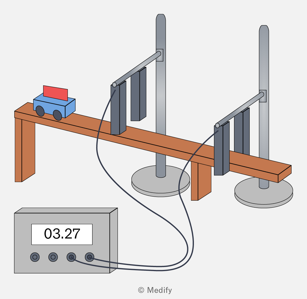
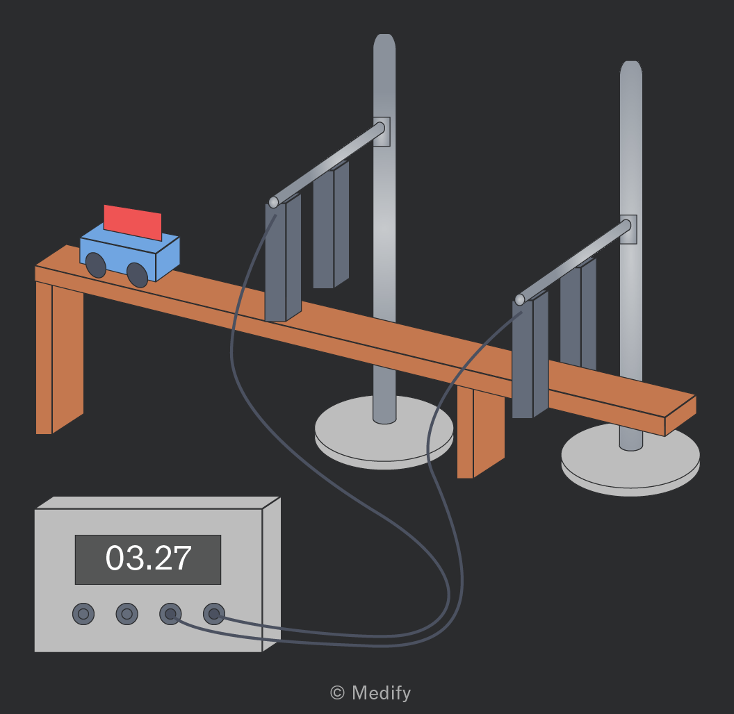
The image shows a setup involving a small blue cart with black wheels and a red rectangle on top, positioned on a wooden track. The track passes through two gate-like structures with black flaps hanging from horizontal bars attached to vertical stands. A cable connects these gates to a gray box with a display showing the number '03.27'. Four buttons are on the front of the box. The setup appears to be an experimental apparatus, possibly for measuring time or speed as the cart passes through the gates.

Light gates are digital timing devices that start or stop an electronic timer or data logger when an infrared beam is interrupted. They eliminate human reaction-time error and are essential when time intervals are too short to be measured reliably with a stopwatch: e.g. free falling object, trolley collisions.

For instantaneous speed, time how long a card of known length takes to break the beam:

For acceleration, use two gates and either two cards or a card with two segments. Ensure the card passes perpendicular to the beam and that ambient light does not trigger the gate; align carefully before timing.

Add to favourites

Digital multimeter

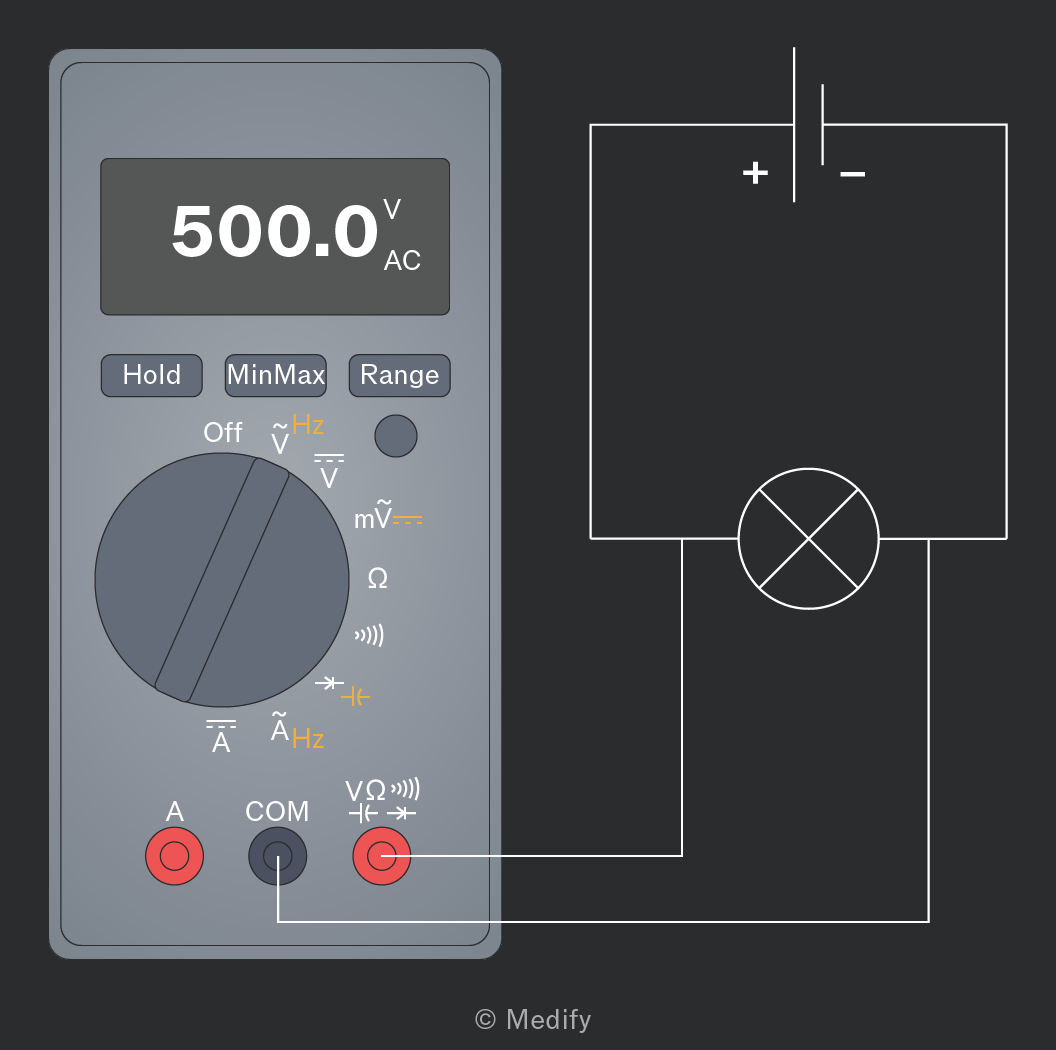
The image shows a digital multimeter with a display reading '500.0 V AC'. The multimeter has several buttons labeled 'Hold', 'MinMax', and 'Range'. A large dial on the multimeter shows various settings, including Off, V for voltage, mV, Ohm for resistance, and Hz for frequency. There are three ports labeled 'A', 'COM', and 'V(Ω)'. Wires from the 'COM' and 'V(Ω)' ports connect to a circuit diagram on the right, featuring a battery symbol with '+' and '-' signs and a circular symbol representing a light bulb.

A digital multimeter (DMM) is a single digital instrument that can be set to measure current, voltage, resistance and (on most models) capacitance. It is the workhorse of A-level electrical practicals: it is used in resistivity, electromotive force/internal resistance and potential-divider experiments.

Always connect the voltmeter setting in parallel and the ammeter setting in series.

Add to favourites

Analogue ammeter

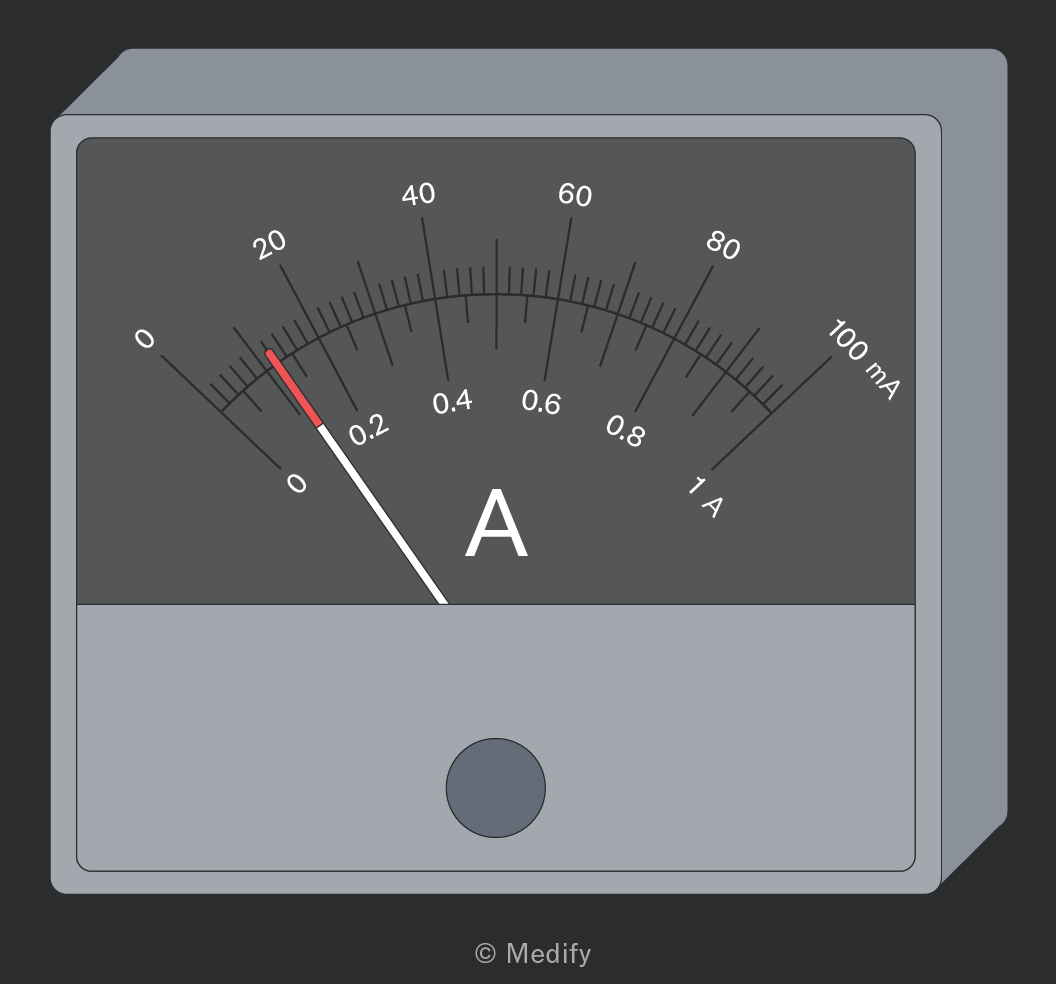
An analog ammeter with a needle pointing to approximately 0.18 on the scale. The scale is marked from 0 to 100 mA on the outer arc and from 0 to 1 A on the inner arc. The scale includes major ticks labeled 0, 20, 40, 60, 80, and 100 mA, and corresponding values 0, 0.2, 0.4, 0.6, 0.8, and 1 A. The center of the meter displays a large 'A' indicating amperes. The needle is red and white, positioned slightly below the 0.2 A mark. The ammeter has a grey casing and a circular knob below the display.

An analogue ammeter measures electric current in a circuit using a moving-coil galvanometer with a calibrated scale. It is always connected in series with the component carrying the current. Typical school models offer ranges such as and on dual scales.

Choose a range where the expected current sits in the upper half of the scale to reduce fractional uncertainty. Read at eye level to avoid parallax.

Add to favourites

Analogue voltmeter

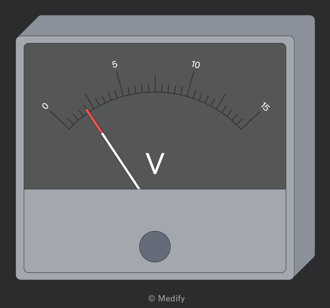
An analog voltmeter displaying a scale from 0 to 15 volts. The scale is marked with intervals at every 1 unit, with larger marks and numbers at 0, 5, 10, and 15. The needle points slightly above the 0 mark. The center of the display has a large letter 'V' indicating volts. The meter has a gray casing with a circular knob or button below the display.

An analogue voltmeter measures the potential difference (p.d.) across a component. It is connected in parallel with the component. School models commonly offer and ranges via a dual scale.

Choose a range where the expected p.d. sits near the upper end of the scale to minimise fractional uncertainty. A voltmeter has very high resistance, so adding it to a circuit branch should not significantly change the current.

Add to favourites

DC power supply

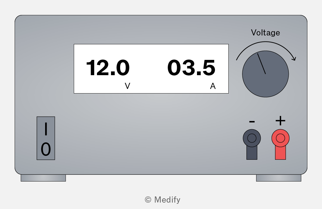
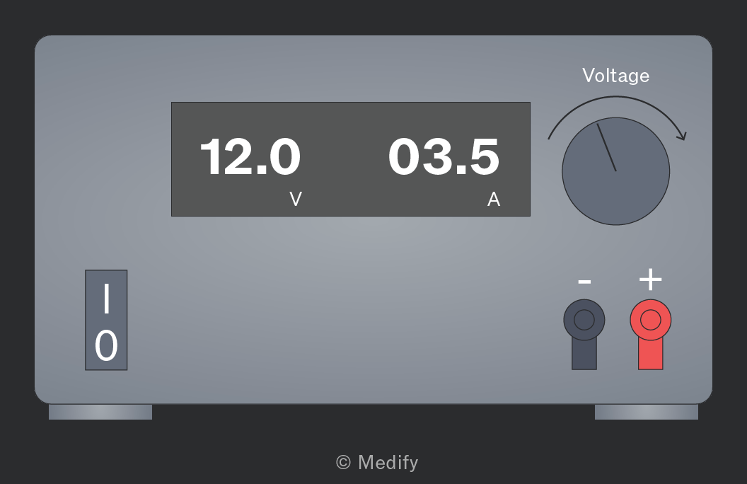
A power supply device showing a digital display with '12.0 V' on the left and '03.5 A' on the right. Above the display, there is a label 'Voltage' with an arrow indicating a clockwise direction, pointing to a round knob. Below the display are two terminals, one labeled with a minus sign and the other with a plus sign. On the left side, there is a switch labeled 'I' and 'O'.

A low-voltage DC power supply delivers a steady, adjustable direct current at outputs typically in the range Most have a built-in voltmeter or ammeter, a variable knob and may include current-limiting protection. They are used in place of cells and batteries for sustained or higher-current work.

Set to the lowest output before switching on. Connect red wires to red terminals and black wires to black terminals. Polarity matters for components such as diodes, electrolytic capacitors and motors. Allow time for the internal resistance of the supply to fall to a steady value before recording readings, and check the output with a multimeter rather than trusting the front-panel display alone.

Add to favourites

Cells and batteries

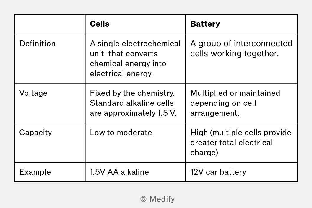
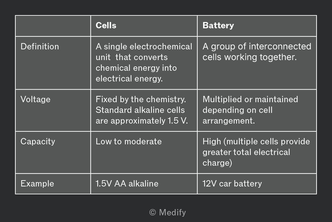
A comparison table with two columns titled 'Cells' and 'Battery'. 

- Definition: 
  - Cells: 'A single electrochemical unit that converts chemical energy into electrical energy.' 
  - Battery: 'A group of interconnected cells working together.'

- Voltage: 
  - Cells: 'Fixed by the chemistry. Standard alkaline cells are approximately 1.5 V.' 
  - Battery: 'Multiplied or maintained depending on cell arrangement.'

- Capacity: 
  - Cells: 'Low to moderate' 
  - Battery: 'High (multiple cells provide greater total electrical charge)'

- Example: 
  - Cells: '1.5V AA alkaline' 
  - Battery: '12V car battery'

The table is © Medify.

Individual cells (e.g. dry cells) and assembled batteries are the standard EMF source for circuits where a stable output and a defined internal resistance are required.

Add to favourites

Variable resistor (rheostat)

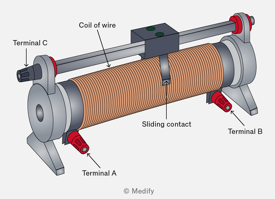
The image shows a cylindrical coil of wire mounted horizontally with labeled components. The coil is wrapped around a central axis and supported by two end brackets. A sliding contact is positioned on top of the coil, connected to a rod running parallel to the coil. Three terminals labeled as Terminal A, Terminal B, and Terminal C are located at different positions around the coil. Terminal A and Terminal B are at the bottom of each end bracket, while Terminal C is on the left side protruding from the end bracket. The coil of wire and sliding contact are labeled with arrows pointing to them. The image is credited to Medify.

A variable resistor is a coil of wire wound on a former, with a sliding contact. It can be connected as:

  • a rheostat with two terminals, A and B, which controls current.
  • a potentiometer with three terminals, A, B and C, which can control p.d. by acting as a potential divider.

Use the rheostat configuration to vary current smoothly through a component when investigating characteristics. Use the potentiometer configuration to access a full range of p.d. from up to the supply voltage. This is essential when characterising a filament lamp or diode near zero.

Add to favourites

Signal generator

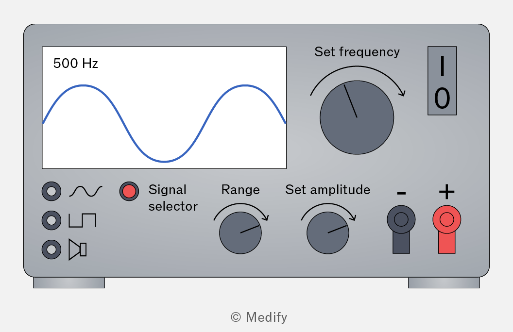
Image of a signal generator with a display showing a sine wave labeled '500 Hz'. Below the display are signal selector buttons with wave symbols and a red button labeled 'Signal selector'. To the right are three knobs labeled 'Range', 'Set frequency', and 'Set amplitude'. There is also an on/off switch labeled 'I' and '0'. Below are two terminals labeled '-' and '+'.

A signal generator produces an alternating output (AC) of selectable waveform (sine, square, triangular), frequency (typically ) and amplitude. It is the standard AC source for driving loudspeakers, vibration generators and microwave transmitters in wave experiments.

Add to favourites

Oscilloscope

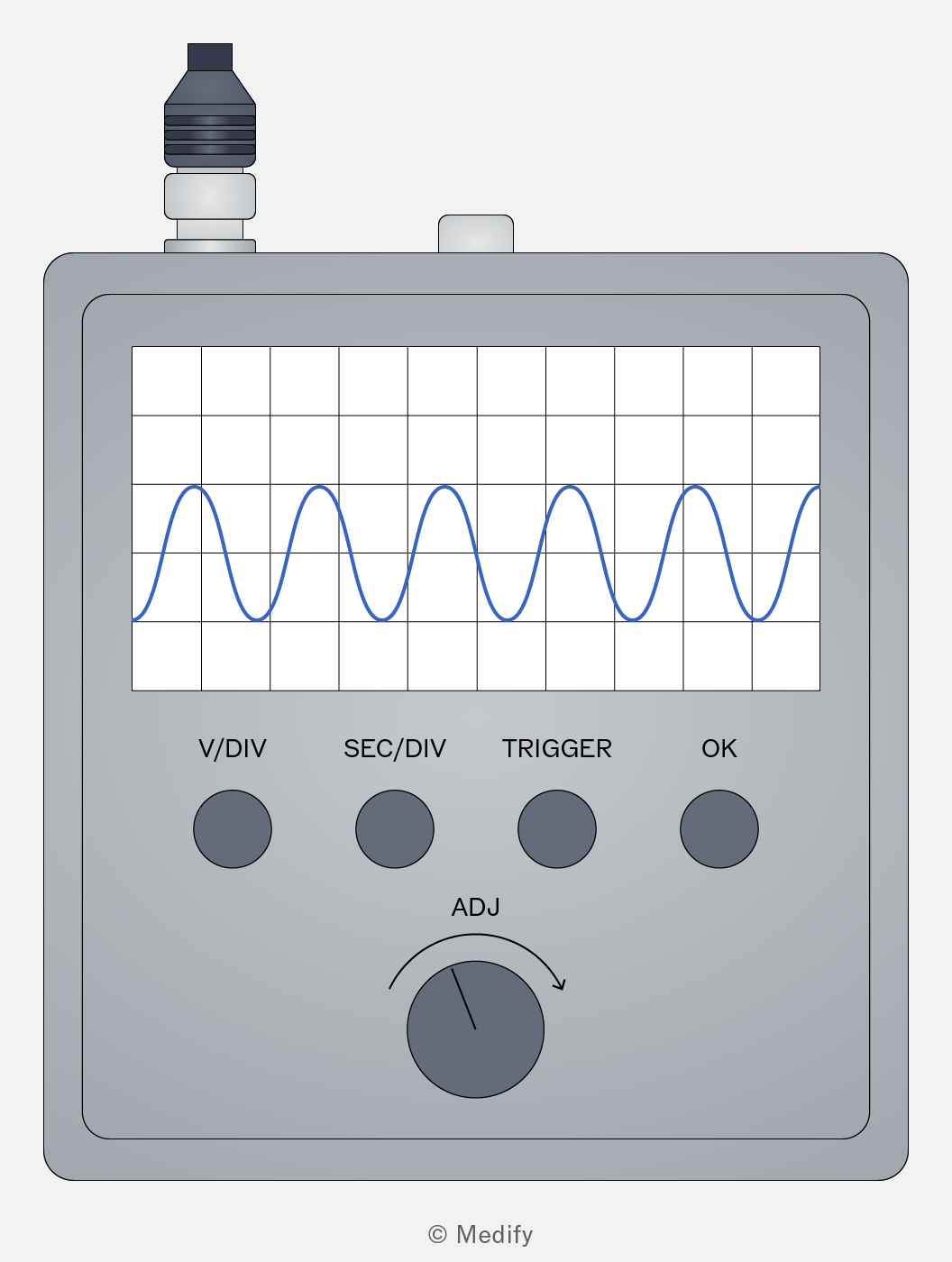
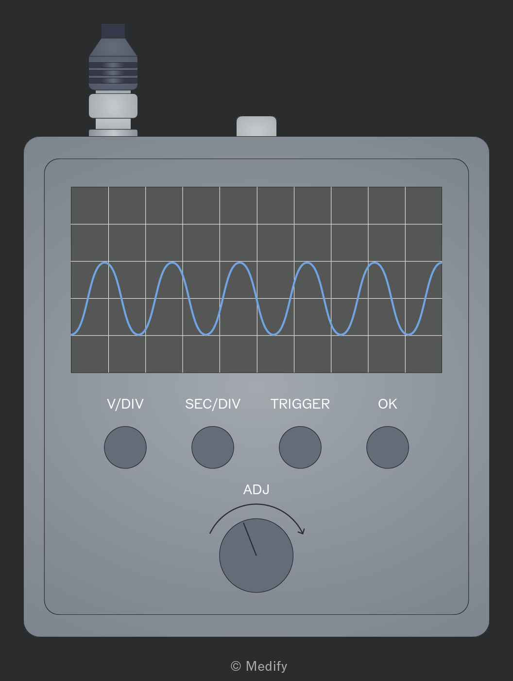
The image shows an oscilloscope with a screen displaying a blue sinusoidal waveform. The grid on the screen is divided into squares with no visible axis labels or numerical values. Below the screen are four round buttons labeled 'V/DIV', 'SEC/DIV', 'TRIGGER', and 'OK'. Below the buttons is a large knob labeled 'ADJ' with an arrow indicating a clockwise rotation.

An oscilloscope displays a voltage–time trace on a screen with a square grid (usually 1 cm divisions). The time-base sets the seconds per horizontal division; the Y-gain (volts/division) sets the vertical scale. It is used to measure amplitude, period (and hence frequency) and phase difference.

Read amplitude as Y-gain multiplied by the number of vertical divisions from the centreline to the peak. Read period as time-base times by the number of horizontal divisions for one complete cycle, then For the best precision, expand the trace so one cycle covers most of the screen.

Add to favourites

Search coil

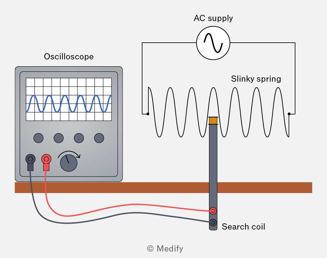
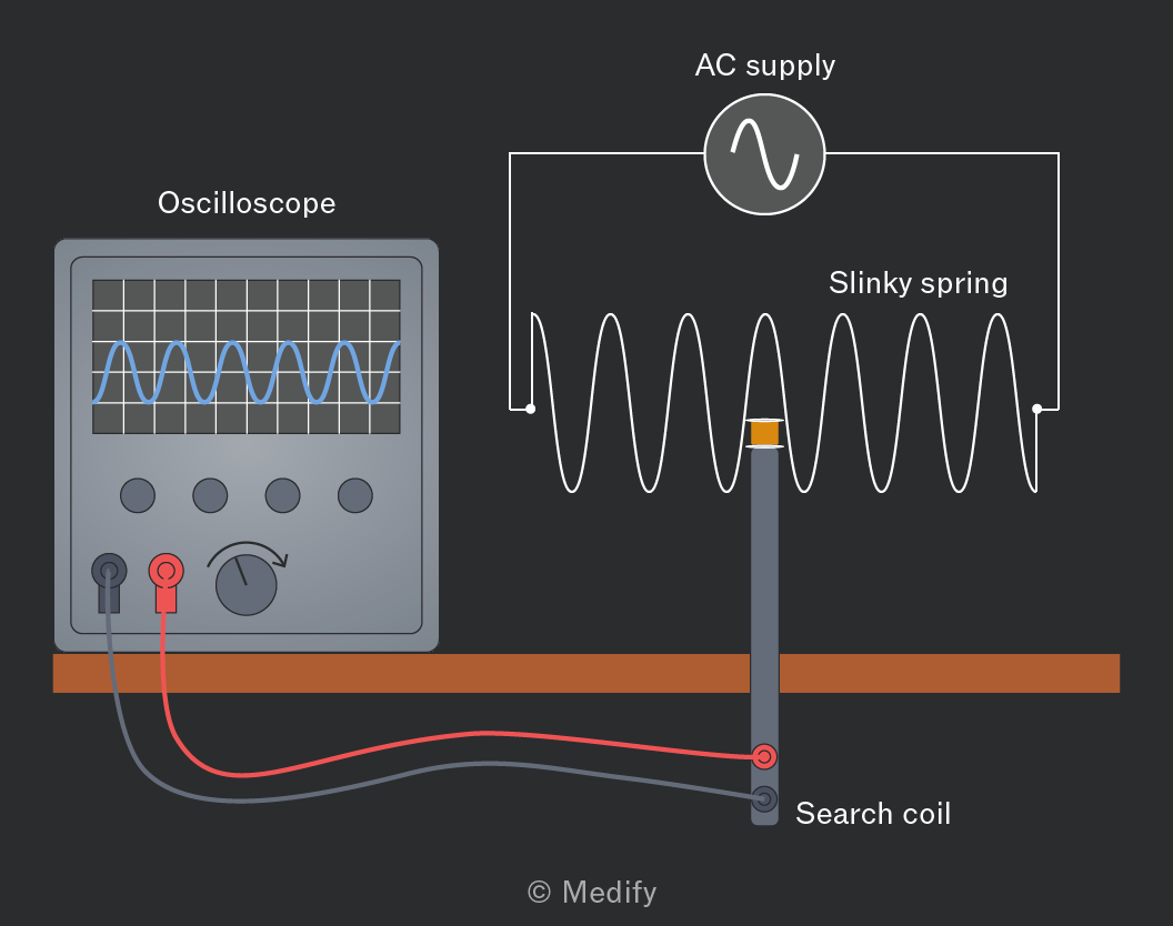
The image shows an experimental setup with an oscilloscope on the left, a slinky spring in the center, and a search coil on the right. The oscilloscope has a display with a grid and a blue waveform. Below the display are four control knobs and two input terminals, one black and one red, connected by wires to a search coil. The search coil is positioned vertically and labeled 'Search coil.' The slinky spring is connected to an 'AC supply,' which is represented by a circle with a sine wave symbol inside. The spring is shown in a zigzag pattern between two connection points. The setup is placed on a wooden surface.

A search coil is a small flat coil of many turns of fine wire, connected to an oscilloscope or sensitive AC voltmeter. When placed in a changing magnetic field, an EMF is induced across its terminals (Faraday’s law). The peak induced EMF is proportional to the peak flux linkage through the coil.

Add to favourites

Microphone and loudspeaker

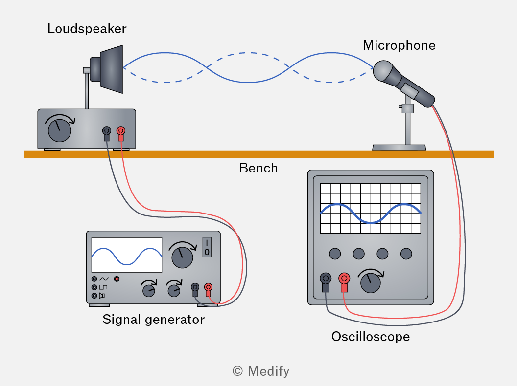
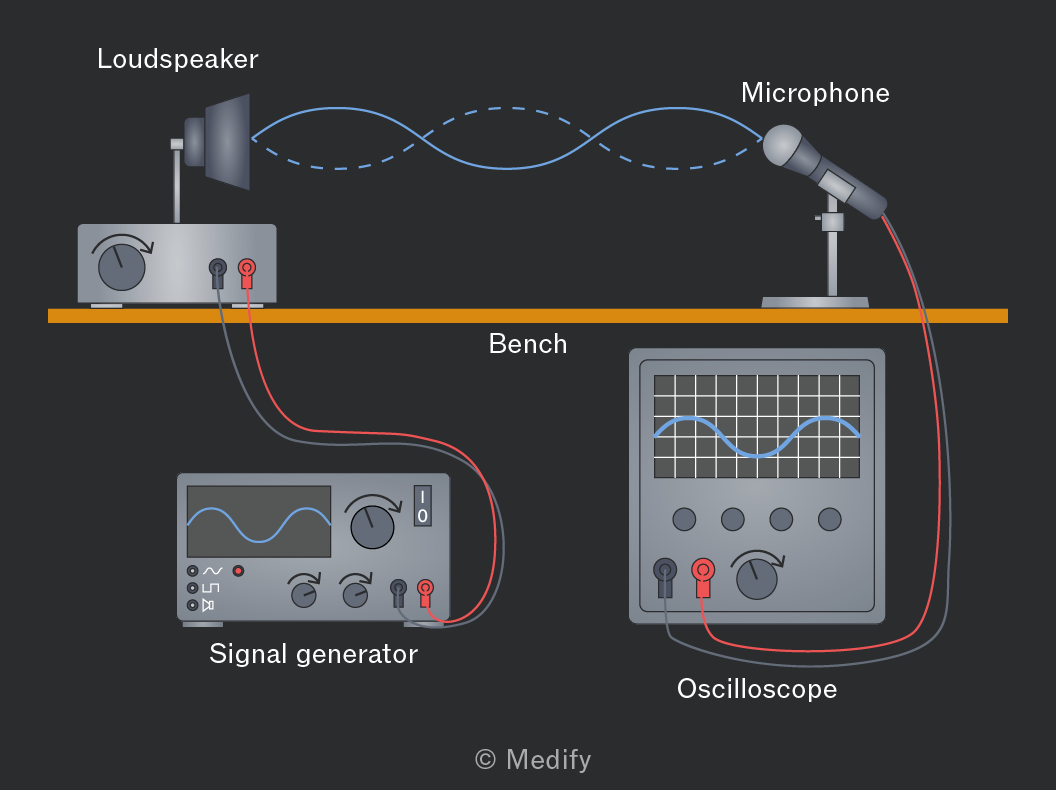
An illustration showing a setup for sound wave analysis. On the left, there is a loudspeaker connected to a device with a dial and red and black terminals. A dashed blue line represents a sound wave traveling from the loudspeaker to a microphone on the right. Below, on a bench, there is a signal generator with a screen displaying a sine wave and several dials and terminals. To the right of the signal generator, an oscilloscope displays a sine wave on its screen. Red and black wires connect the devices. Labels include 'Loudspeaker,' 'Microphone,' 'Bench,' 'Signal generator,' and 'Oscilloscope.'

A loudspeaker (driven by a signal generator) is the standard source of sound waves at chosen frequencies. A microphone converts incident sound back into an electrical signal that can be displayed on an oscilloscope or analysed by a data logger. Together they allow quantitative sound-wave experiments.

Add to favourites

Ripple tank

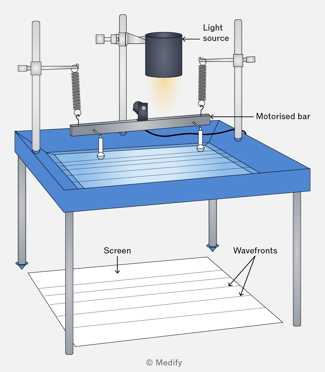
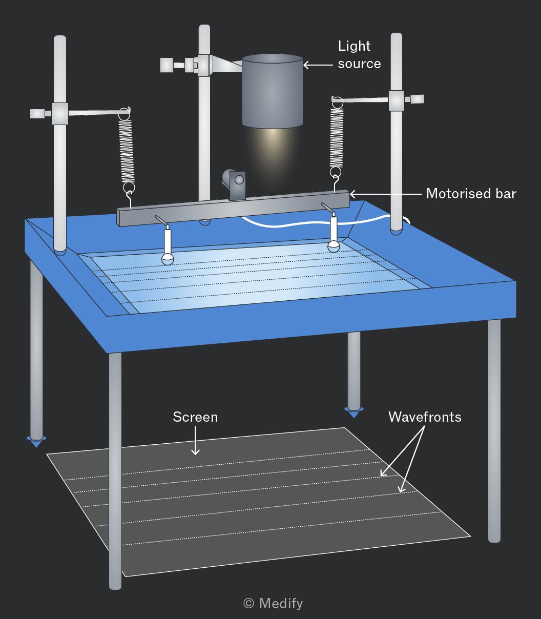
The image shows a wave tank setup with a blue rectangular tank supported by four legs. Above the tank, there is a motorised bar connected to two vertical rods with springs. A cylindrical light source is positioned above the bar, labeled 'Light source.' The bar is labeled 'Motorised bar.' Below the tank, there is a screen labeled 'Screen' with horizontal lines, labeled 'Wavefronts,' representing waves projected onto the screen.

A ripple tank is a shallow, transparent tank of water with a vibrating dipper (or straight bar) driven by a small motor. Ripples on the surface are projected onto a screen below by an overhead lamp, allowing wave behaviour to be observed:

  • reflection
  • refraction
  • diffraction
  • two-source interference.
Add to favourites

Vibration generator

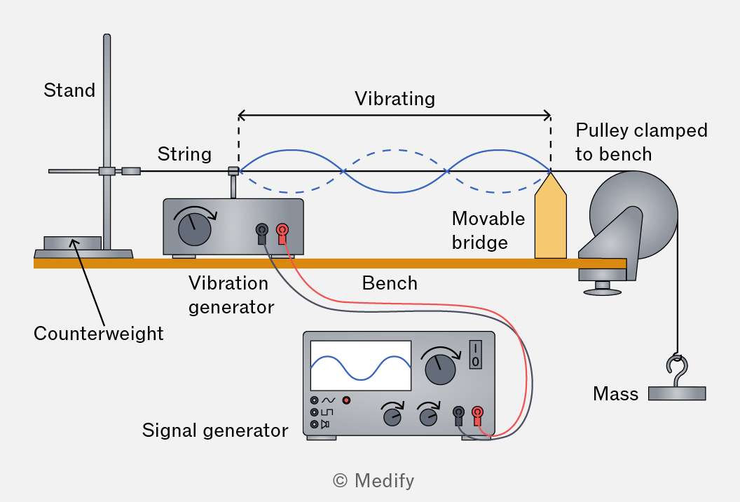
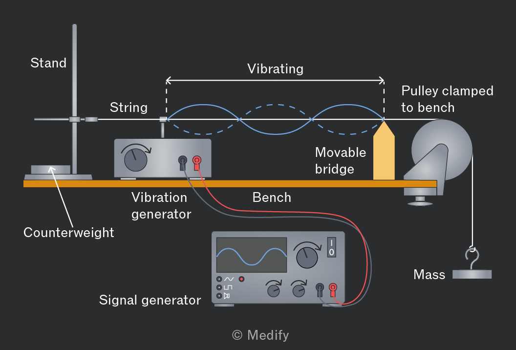
The image shows a setup for a physics experiment involving a vibrating string. A string is attached to a vibration generator, which is connected to a signal generator. The string passes over a movable bridge and a pulley clamped to a bench, with a mass hanging from the end of the string. The setup includes a stand with a counterweight on the left side. The string is labeled 'Vibrating' with a wave pattern depicted along it. The components are arranged on a bench, with the vibration generator and signal generator placed on the surface. Each component is labeled accordingly, including 'Stand', 'Counterweight', 'Vibration generator', 'Signal generator', 'Movable bridge', 'Pulley clamped to bench', and 'Mass'.

A vibration generator (or vibration transducer) is essentially a small loudspeaker without a cone, with a drive rod fixed to its diaphragm. Driven from a signal generator, it produces controlled mechanical oscillations used to set up stationary waves on a string or in a stretched wire.

Adjust the frequency of the signal generator until a clear stationary wave appears. Avoid resonance amplitudes large enough to detach the string.

Add to favourites

Microwave transmitter and receiver

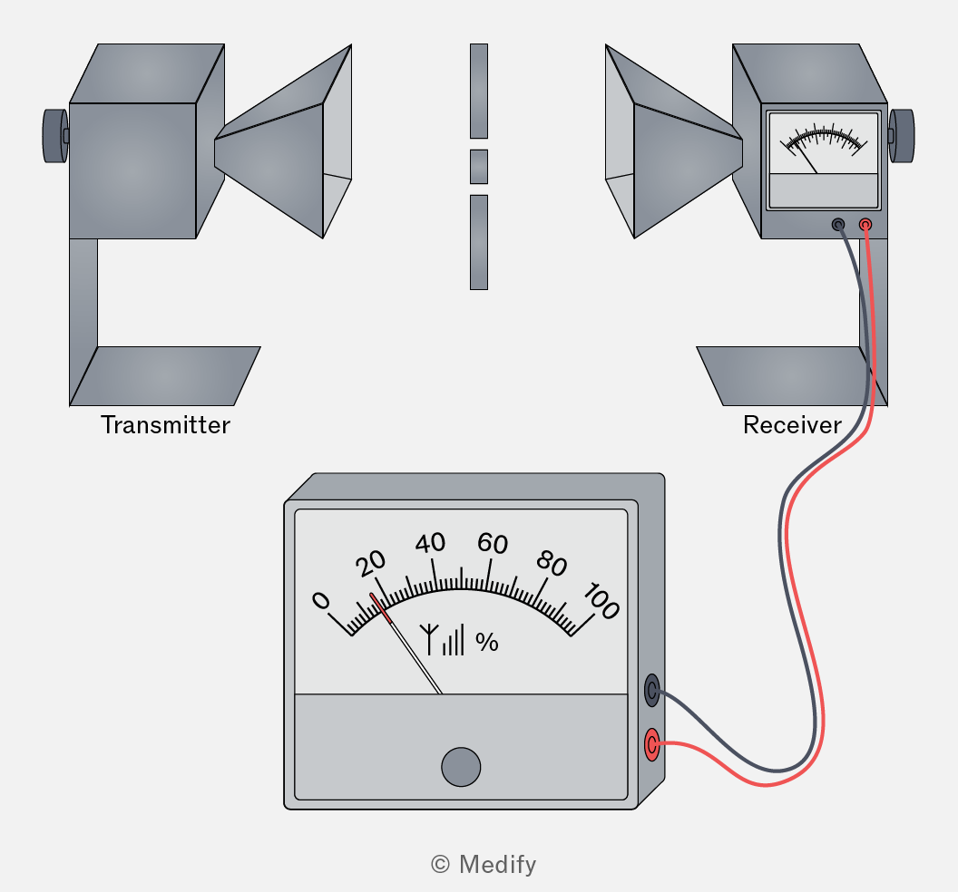
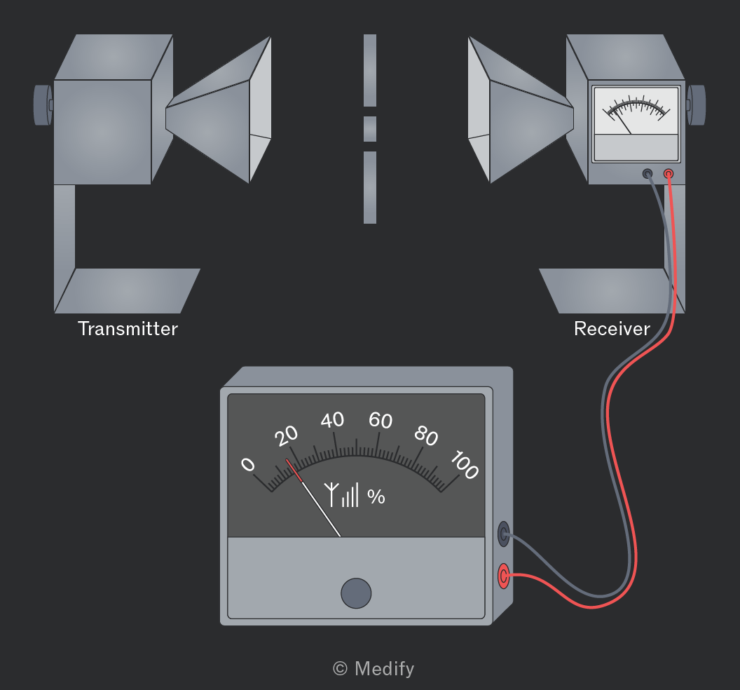
The image depicts a setup with a transmitter on the left and a receiver on the right, both facing each other. Between them are three rectangular obstructions. The transmitter is labeled 'Transmitter' and the receiver is labeled 'Receiver'. The receiver is connected by wires to a meter below, which displays a scale from 0 to 100 labeled with 'γ' followed by '%'. The needle on the meter points to approximately 20% on the scale.

A microwave kit consists of a Gunn diode transmitter (typically with a wavelength of ) and a receiving probe connected to an amplifier or meter. The relatively long wavelength makes it ideal for demonstrating interference, diffraction, standing waves and polarisation on a macroscopic scale.

Add to favourites

Resonance tube

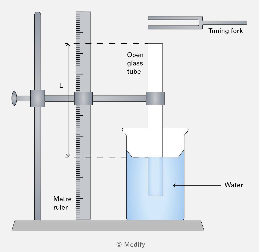
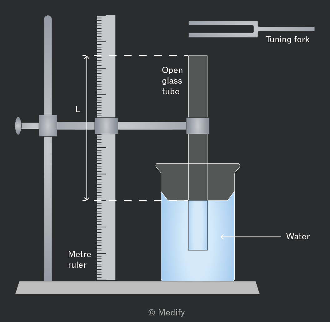
The image shows an experimental setup consisting of a vertical open glass tube partially submerged in a beaker filled with water. To the left, a vertical meter ruler is positioned alongside the glass tube, with a horizontal clamp holding the tube in place. The ruler is marked in units, but specific values are not visible. A dashed line indicates the water level inside the beaker. The distance labeled 'L' is marked between the top of the water inside the tube and a point on the ruler. At the top right corner, an illustration of a tuning fork is shown, labeled 'Tuning fork'. The water inside the beaker is labeled 'Water'. The setup is mounted on a base labeled with © Medify.

A resonance tube is a vertical glass tube closed at one end (often by adjusting the water level inside) with a sound source held above the open end. When the source frequency matches a natural frequency of the air column, a stationary wave forms and the sound is audibly louder than the source. This is resonance.

Add to favourites

Laser

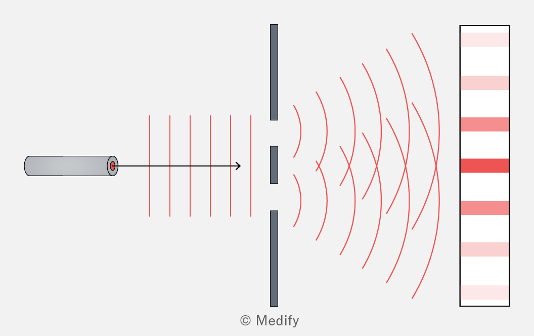
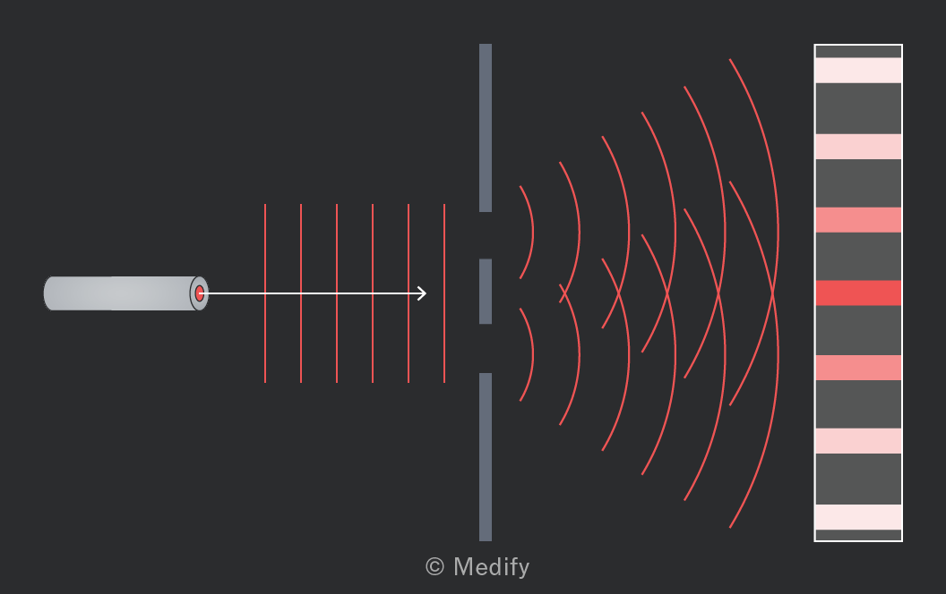
The image depicts a double-slit experiment. On the left, a cylindrical object emits a wave represented by red lines. These lines pass through two vertical slits in a barrier, creating diffracted waves that spread out on the right. The diffracted waves form an interference pattern on a screen, shown as alternating dark and light bands.

A laser is a coherent, monochromatic, highly collimated light source. School lasers are generally red diode lasers ( or green diode-pumped lasers They are the source of choice for Young’s double-slit, single-slit diffraction and diffraction grating experiments.

Add to favourites

Diffraction grating

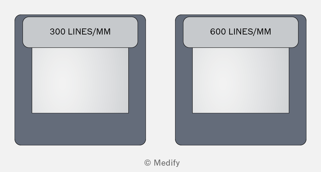
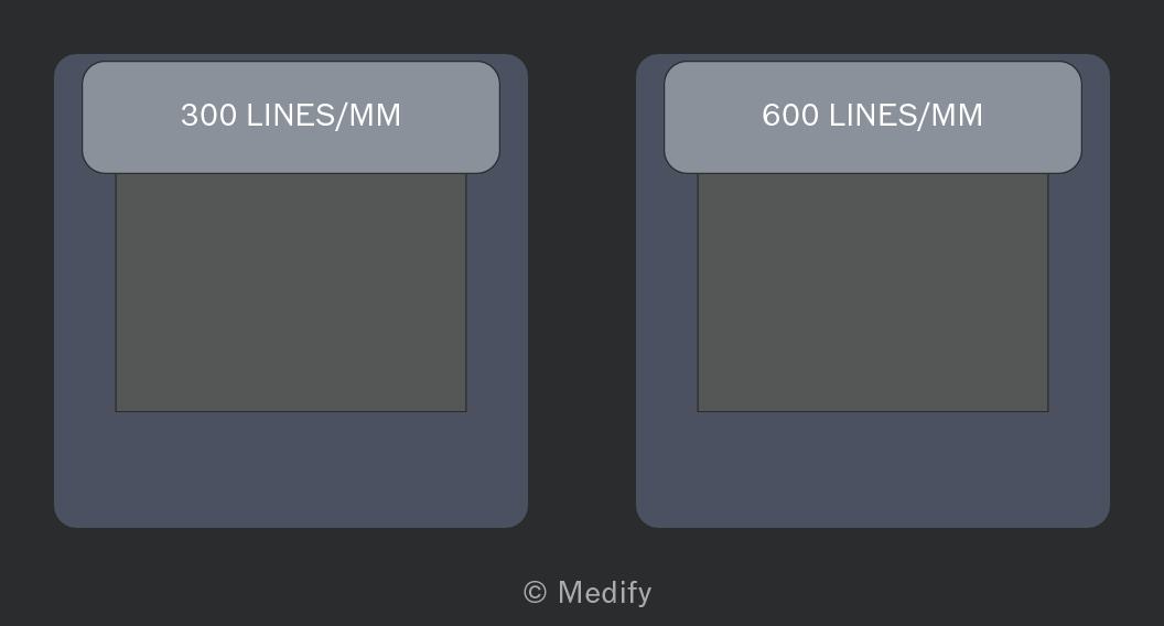
The image displays two rectangular objects side by side. The object on the left is labeled '300 LINES/MM' and the one on the right is labeled '600 LINES/MM'. Both labels are placed at the top of each rectangle. There is no other visible text or markings on the objects.

A diffraction grating is a glass or plastic slide with a large number of equally spaced parallel lines (typically 300 to 600 lines per mm). When monochromatic light passes through, it produces sharp, bright maxima at angles given by the diffraction grating equation.

Add to favourites

Polariser

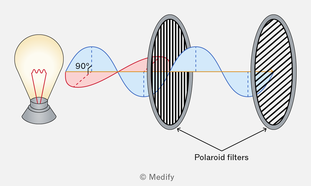
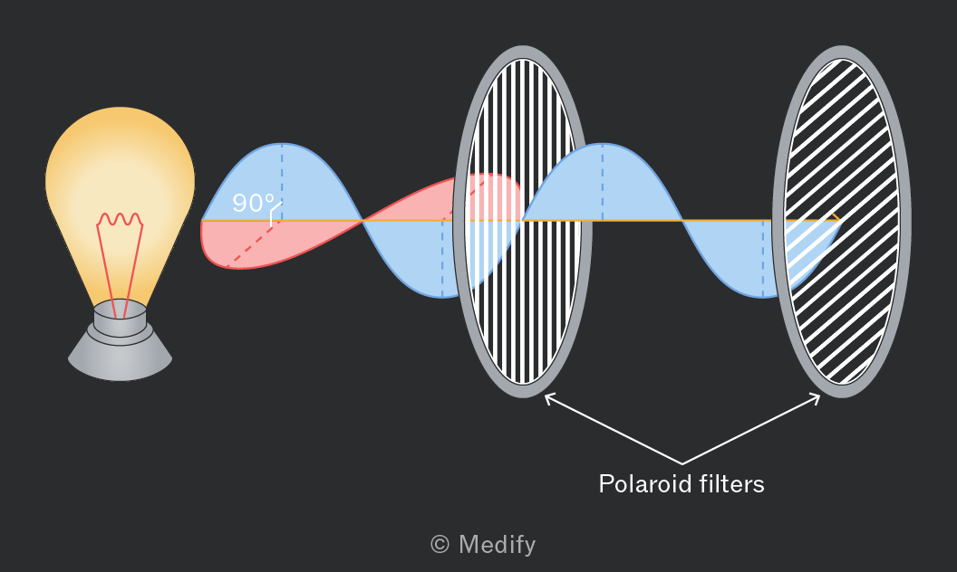
The image shows a diagram of light polarization. A light bulb on the left emits a wave depicted in red and blue, representing light waves at a 90° angle to each other. The wave passes through two vertical polaroid filters, illustrated as two oval shapes with black vertical lines. The wave becomes polarized after passing through the filters, shown by a blue wave aligned with the vertical lines of the filters. An arrow labeled 'Polaroid filters' points to the filters. The image is credited to Medify.

A polariser is an optical filter that transmits only the component of incident light vibrating along its transmission axis, blocking the perpendicular component. Two polarisers in sequence demonstrate that light is a transverse wave; when their axes are crossed (at ), no light is transmitted

Add to favourites

Geiger–Müller (GM) tube and counter

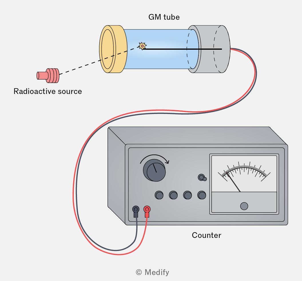
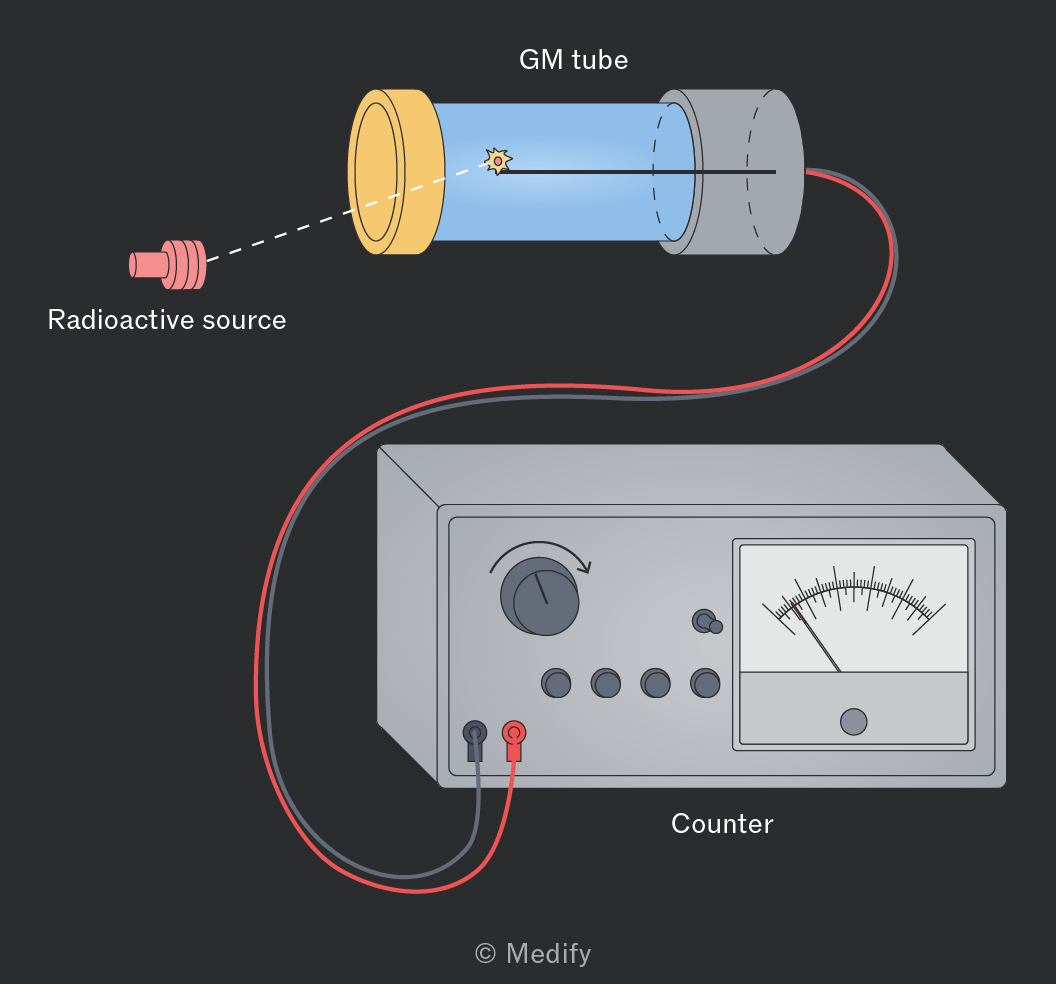
The image shows a Geiger-Müller (GM) tube setup with a radioactive source positioned on the left, emitting radiation towards the GM tube on the right. The GM tube is connected by wires to a counter device below, which has a dial, several buttons, and a gauge with a needle. The GM tube is labeled 'GM tube' and the radioactive source is labeled 'Radioactive source'. The counter device is labeled 'Counter'.

A Geiger–Müller (GM) tube is a detector of ionising radiation (α, β and γ). Each ionising event produces a pulse, which is registered by a counter (total counts in a chosen time) or a ratemeter (counts per second).

SAFETY: Handle sealed sources with tongs, keep them in their lead-lined storage when not in use, and minimise exposure time and handling distance. Always measure and subtract background count rate. The GM tube has a dead time so the maximum reliable count rate is limited; check sources of systematic error before taking measurements.

Add to favourites