
Physics of the eye (3.10.1)
On this page
The diagram below shows the internal structure of the human eye.
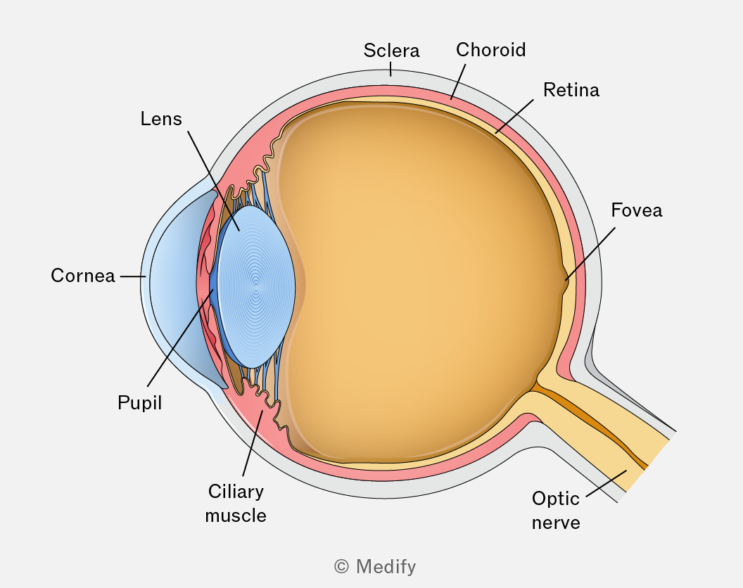
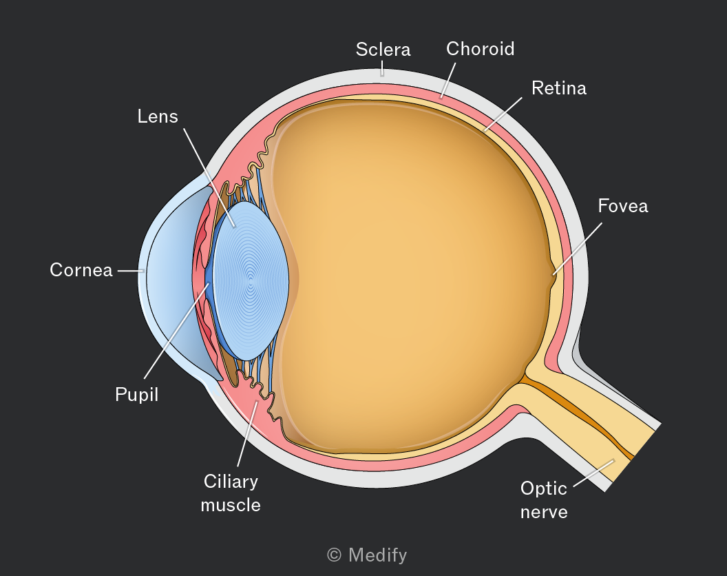
The table below identifies and describes the parts of the eye you should know for your exams:
| Part of the eye | Description |
|---|---|
| Cornea | Transparent front part of the eye where light enters. It is responsible for most of the eye’s focusing/refraction. |
| Pupil | The opening in the centre of the iris that allows light to enter the eye. Its size changes depending on light intensity. |
| Iris | Coloured part of the eye that controls the size of the pupil, regulating how much light enters. |
| Lens | Transparent structure behind the pupil that changes shape to fine-tune focus on near and distant objects. |
| Ciliary muscles | Muscles that change the shape of the lens during focusing. |
| Suspensory ligaments | Fibres that hold the lens in place and help change its shape by altering tension. |
| Retina | Light-sensitive layer at the back of the eye where the image is formed. Contains rods and cones. |
| Optic nerve | Carries electrical signals from the retina to the brain, where they are interpreted as images. |
| Sclera | Tough, white outer layer that protects the eye and helps maintain its shape. |
| Choroid | Layer containing blood vessels that supply the eye with oxygen and nutrients. Its dark pigment reduces internal reflection. |
| Aqueous humour | Watery fluid between the cornea and lens that helps maintain the eye’s shape. |
| Vitreous humour | Jelly-like fluid between the lens and retina that helps maintain the spherical shape of the eye. |
The light-sensing cells in the retina, known as photoreceptors, function by reacting to light via specialised light-sensitive chemical pigments. When light is incident upon them, these pigments are activated and then become bleached. This leads to electrical signals, which pass through nerve cells in the retina and then travel to the brain via the optic nerve.
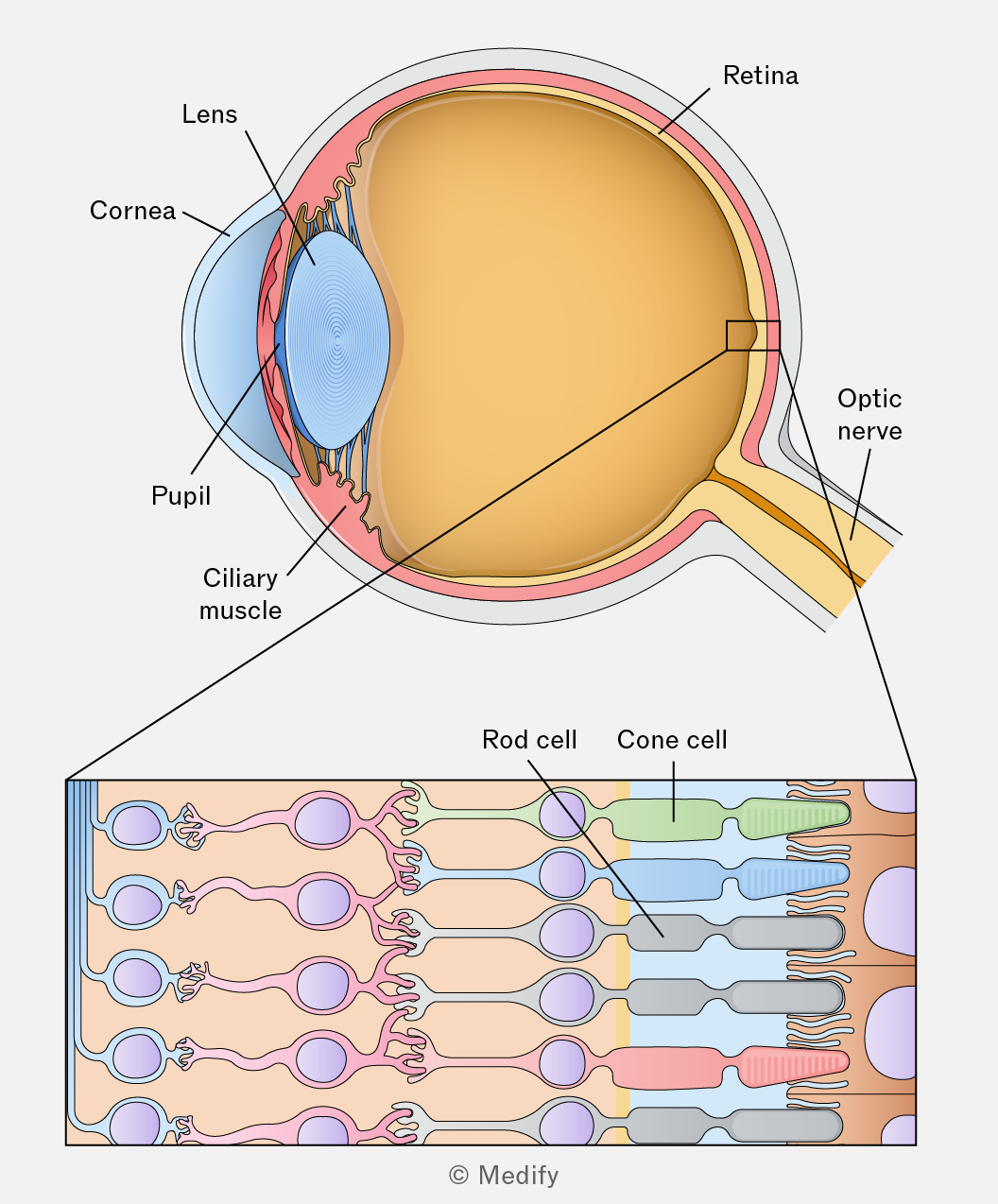
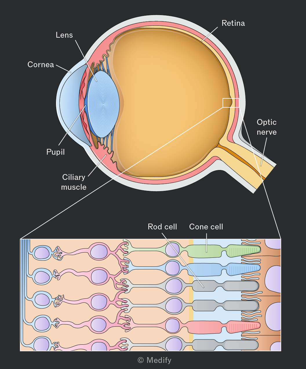
It is useful to note that the chemical pigments are regenerated, or unbleached, by enzymes using vitamin A-containing substances from the blood after light is incident upon it.
The retina (at the back of the eye) contains two main types of light-sensitive cells:
| Property | Rods | Cones |
|---|---|---|
| Light intensity detected | Low intensity | High intensity |
| Types | One type | Three types: red, green and blue |
| Vision produced | Greyscale vision with little detail | Detailed colour vision |
| Number (approx.) | 120 million | 5 million |
| Nerve fibre connection | Several rods connect to a single nerve fibre | A single cone connects to a single nerve fibre |
| Distribution | Concentrated in peripherary of the retina | Highly concentrated in the fovea |
It is useful to note the blind spot (optic papilla) located directly on the retina, is where the optic nerve leaves the eye. It contains no rods or cones, so it is not sensitive to light.
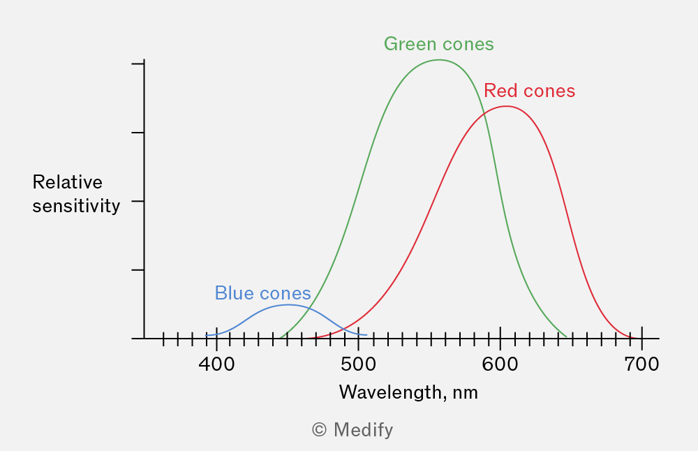
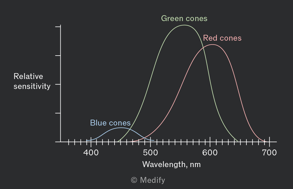
Cone cells are responsible for colour vision. The red, green and blue type cone cells are responsible for absorbing different ranges of light wavelengths.
The human eye is more responsive to red and green light. Thus, blue light often appears dimmer due to the reduced sensitivity. The brain receives signals from the three types of cone cells via the optic nerve and interprets their weighted strengths as colour.
It is useful to know that the human eye is more sensitive to red and green light because the eye’s optics scatter and absorb blue light more. Moreover, there is a higher concentration of red and green-sensitive cone cells in the central retina.
The plot below shows the weighted strengths vs. wavelength for the three types of cone cells.
Any colour can be interpreted by the brain as a combination of different intensities of red, green, and blue light.
For example, when receiving a strong signal from the red cones, a medium signal from the green cones, and no signal from the blue cones, the brain interprets this as yellow colour.
Spatial resolution is a measure of the eye’s ability to form separate images of objects that are close together.
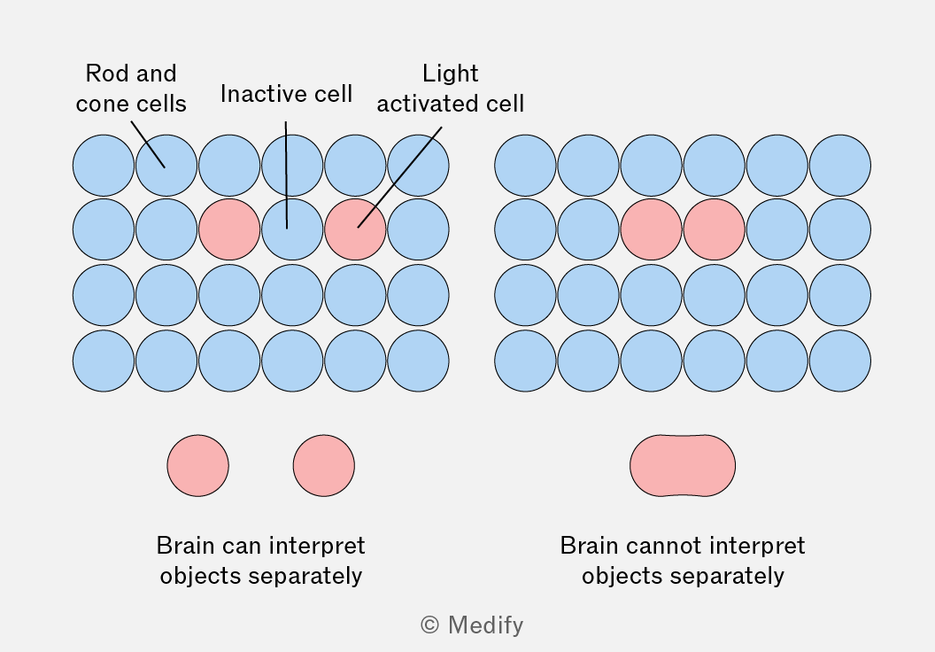
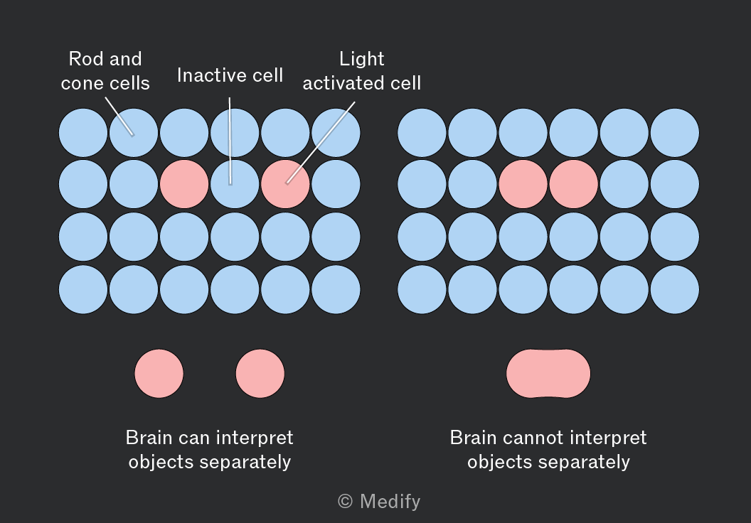
Photoreceptor cells in the retina are responsible for distinguishing between closely spaced objects. Two objects can only be distinguished if their images fall on separate photoreceptors, with at least one unstimulated rod or cone between them.
If there is no inactive cell between the light from different objects, the brain cannot distinguish them and views them as a single object, as shown in the diagram below.
- The fovea, at the centre of the retina’s yellow spot, offers the sharpest vision due to densely packed, brain-connected cone cells. The fovea contains only cones and no rods.
- In dim light, cones are ineffective, and rods take over. Since the yellow spot lacks rods, viewing faint objects directly is difficult. Looking slightly to the side shifts the image to rod-rich areas, improving detection.
Lenses are used to change the direction of light rays by refraction. There are two main types of lenses:
- Converging (convex) lens: brings light rays to a focus.
- Diverging (concave) lens: causes light rays to spread out.
The human eye contains a converging lens, so it brings the light rays entering the eye closer together.
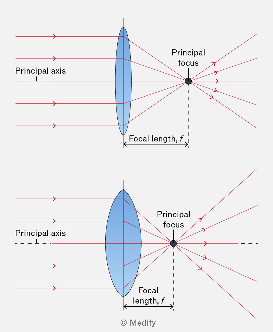
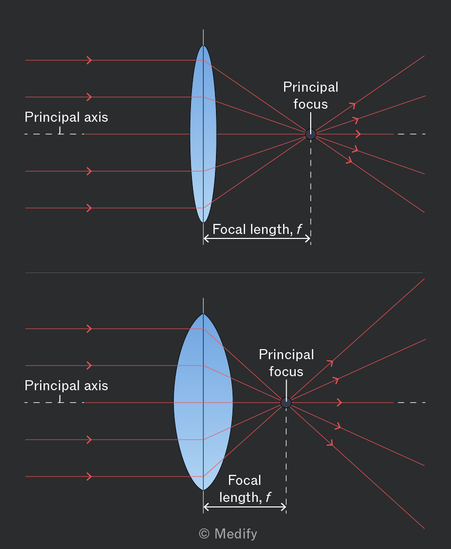
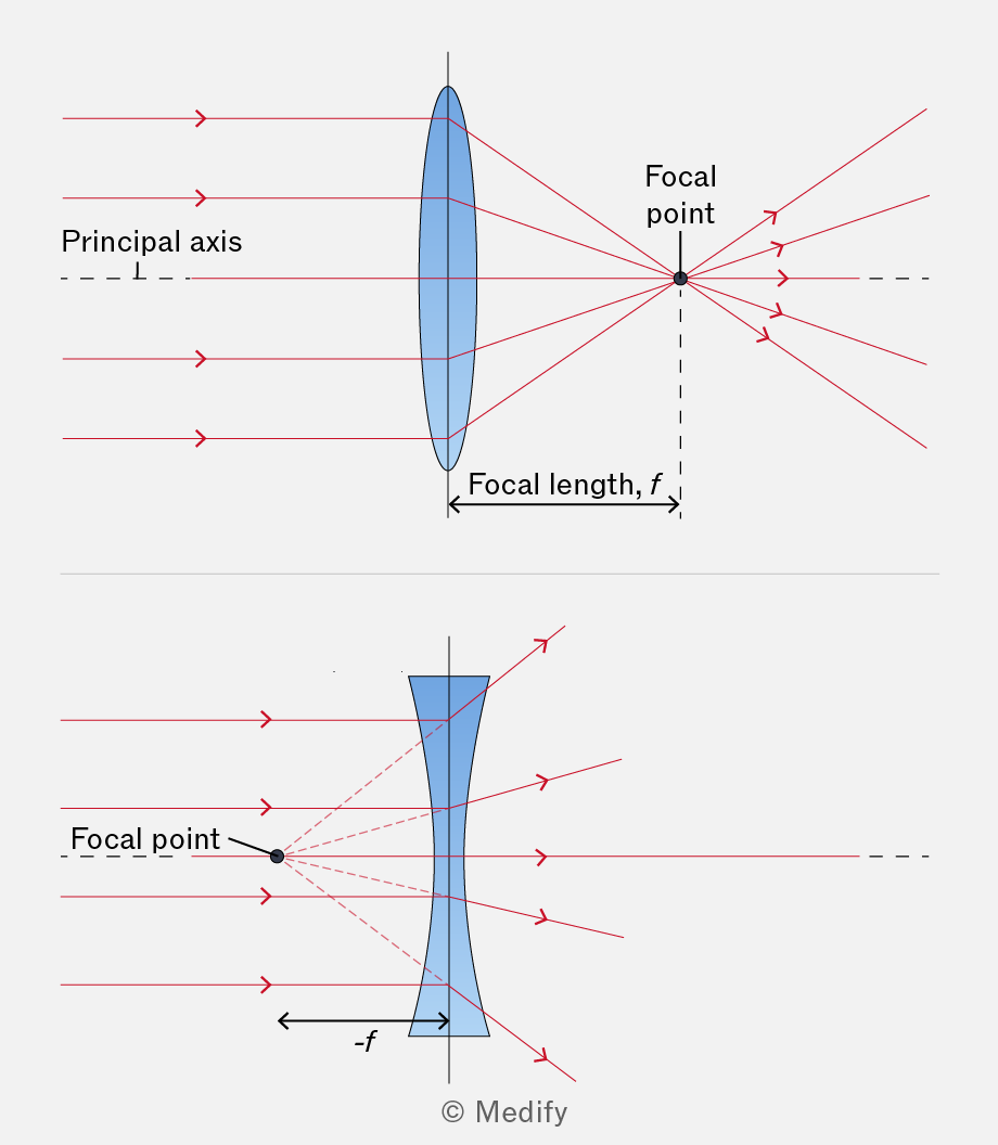
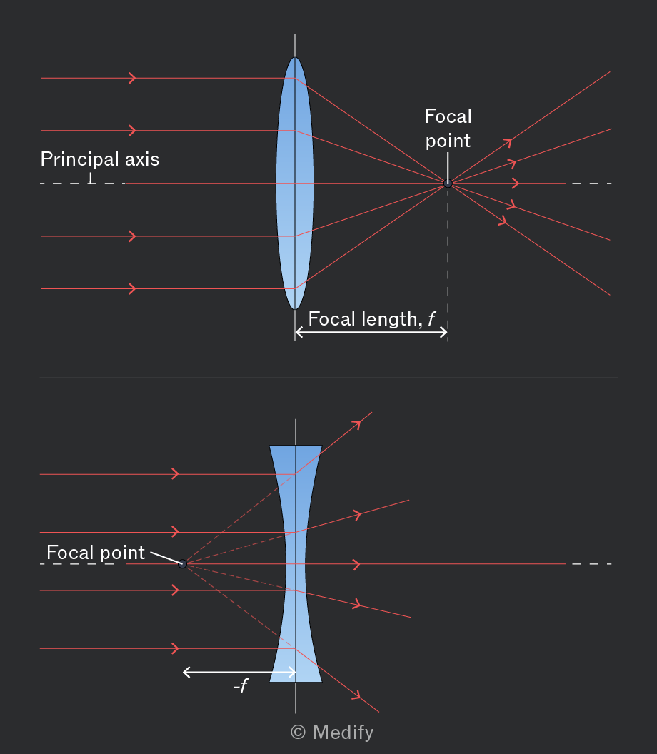
When incident light rays are parallel to the principal axis, a converging lens focuses them to a single point, known as the principal focus, also called the focal point, as illustrated in the diagram below.
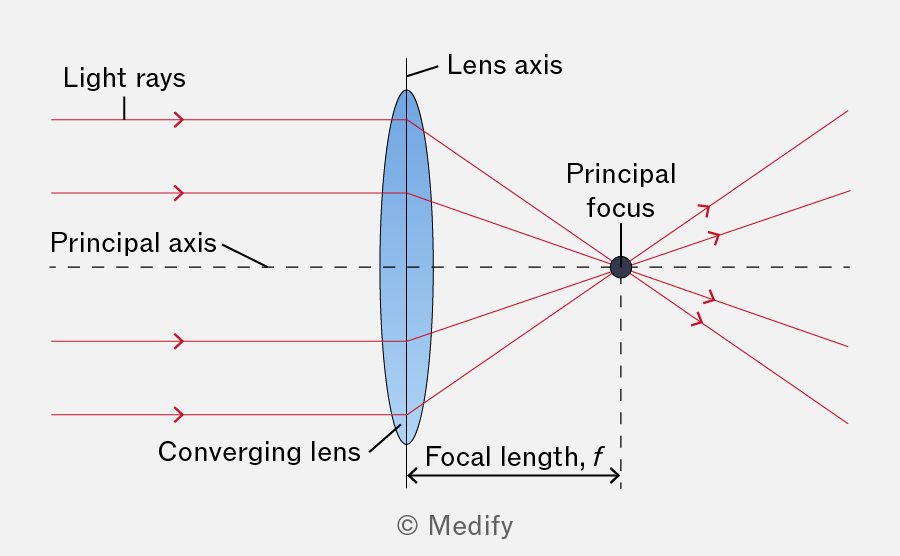
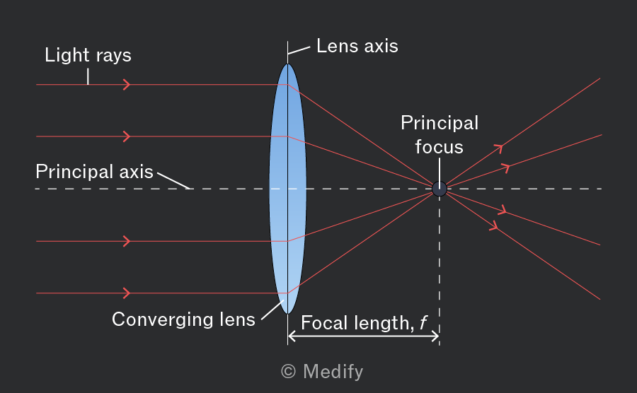
The focal length is the distance between the optical centre of the lens and the principal focus.
To find where the image is formed by a converging lens using a ray diagram drawn to scale.
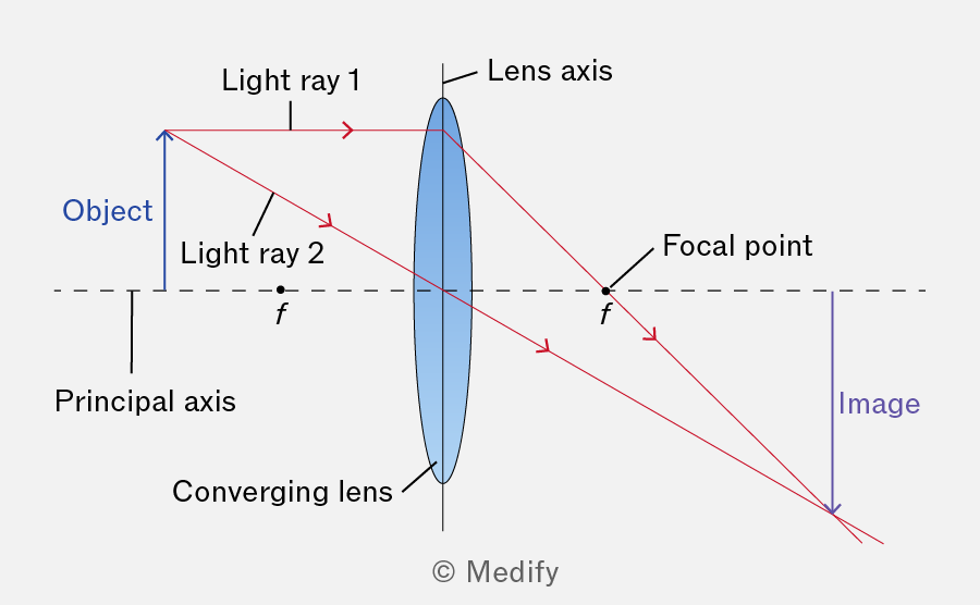
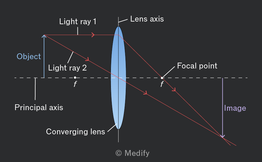
The object is drawn as an arrow above the principal axis. Two light rays are drawn from the top of the object and pass through the lens, creating an image.
For a converging lens, the light rays obey the following rules:
- Light ray 1: This ray travels from the tip of the object to the lens parallel to the principal axis, and refracts towards the axis passing through the focal point on the other side of the lens.
- Light ray 2: This ray passes straight from the tip of the object through the centre of the lens, and its path is not affected.
The top of the image is formed where the two light rays meet.
To find the location of where an image is formed by a diverging lens, it is helpful to draw a ray diagram to scale.
The object is drawn as an arrow above the principal axis. Two light rays are drawn from the top of the object and pass through the lens, creating an image.
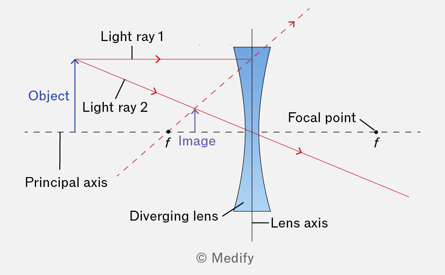
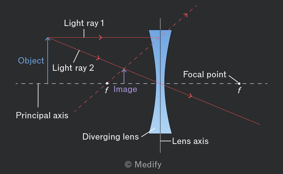
For a diverging lens, the light rays obey the following rules:
- Light ray 1: This ray travels from the tip of the object to the lens parallel to the principal axis and refracts away from the axis, appearing to have come from the principal focal point.
- Light ray 2: This ray passes from the tip of the object straight through the centre of the lens, and its path is not affected.
The top of the image is formed where the backward extensions of the two refracted rays meet. The image formed through a diverging lens is virtual (i.e. it cannot be projected onto a screen) and upright.
The focal length of a lens can be determined by the thin-lens equation:
Where:
- is the focal length (m)
- is the object distance (m)
- is the image distance (m).
When using the thin-lens equation for:
- converging lenses, and are always positive, and is negative for a virtual image and positive for a real image.
- diverging lenses, and are always negative, is always positive.
It is important to note that this equation can be applied to the human eye.
The power of a lens is defined as its ability to refract light; the greater the power of a lens, the more light it refracts. This can also be applied to the lens of the eye:
Where:
- is the power of the lens in dioptres , and
- is the focal length in .
Power and focal length are inversely proportional to each other. A shorter focal length refracts light rays passing through the lens more strongly.
The far point is defined as the furthest distance at which the eye can comfortably focus. For individuals with normal vision, the far point is considered to be at infinity. When the eye is focused on the far point, it is said to be unaccommodated (i.e. the ciliary muscles are fully relaxed).
The near point is defined as the closest distance at which the eye can comfortably focus. This value changes as the eye ages and is approximately for younger eyes and for healthy adults.
Multiple parts of the eye are responsible for focusing light rays. Therefore, they can be combined and modelled as a single converging lens. The power of all these components can be summed to yield a single value for the eye’s power.
The power of the eye at the far point is equal to approximately , giving a focal length of This total power is the sum of:
- the cornea (around )
- the lens (around )
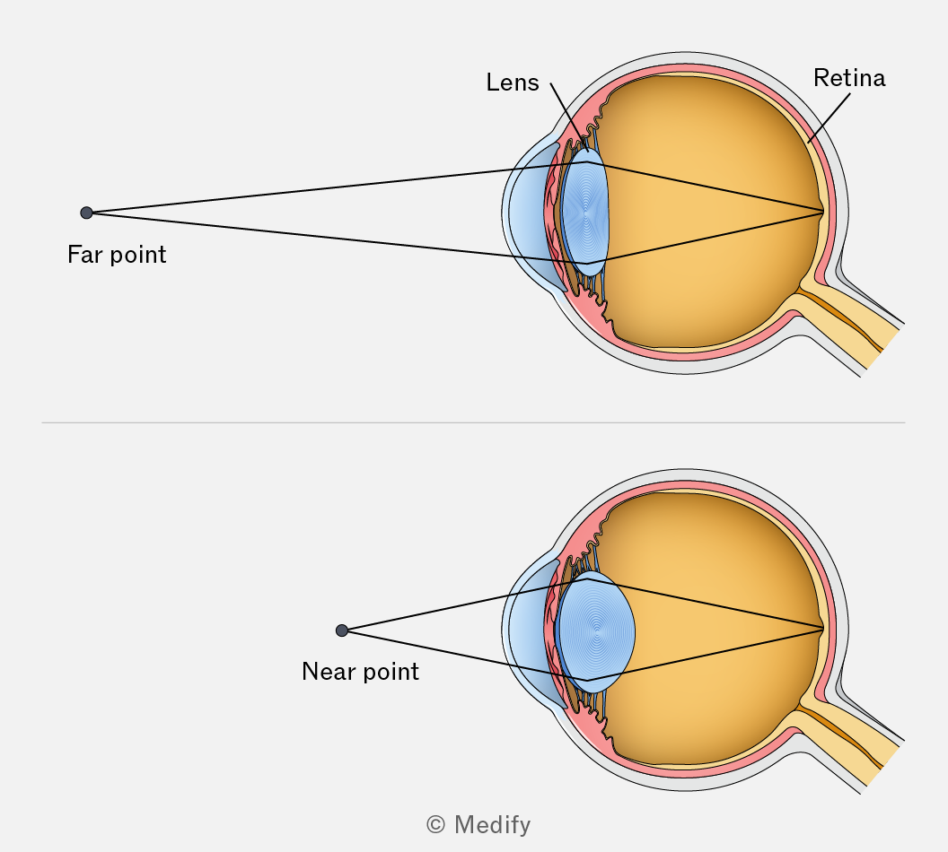
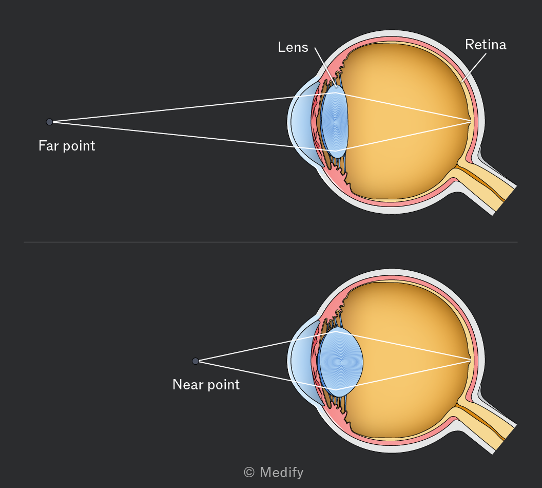
When the eye is focused on nearby objects, the eye’s power increases as the ciliary muscles contract, causing the lens to become thicker (more convex). As a result, the focal length decreases. However, the distance from the optical centre of the lens to the image remains essentially constant.
Question walkthrough
Finding image distance in the eye
Uses P=1/f to find the eye’s focal length from its power, then the lens equation with the object at infinity to show the image distance equals the focal length in an unaccommodated eye.
Lenses can produce either real or virtual images:
- A real image is formed when the light rays from an object converge at a point after passing through a lens. A real image can be projected onto a screen.
- A virtual image is formed when the light rays from an object appear to come from a point, but they do not actually meet or converge. A virtual image cannot be projected onto a screen.
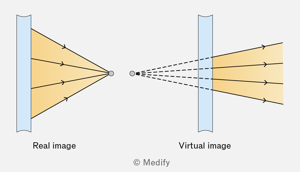
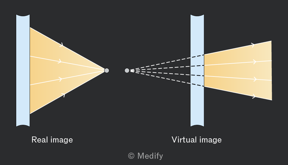
Real and virtual images are created using a converging lens. However, a diverging lens can only form virtual images and cannot form a real image.
- Converging lenses always have a positive focal length
- Diverging lenses always have a negative focal length
This depends on the shape of the lens, not the image it forms.
Converging lenses can produce both real and virtual images, depending on the object’s position relative to the focal length:
- if the object is beyond the focal length, a real image is produced
- if the object is within the focal length, a virtual image is produced.
Diverging lenses have a negative focal length, so they can only ever produce virtual images.
The linear magnification defines how much larger or smaller the image is compared to the object and is calculated by:
Where:
- the linear magnification is a unitless quantity,
- the image distance is in , and
- the object distance is in .
The nature of the magnification can be checked using the following conditions:
- If the image is magnified.
- If the image is reduced.
- If the image’s size is equal to the object’s size.
It is important to note that the above expression can be used as is for virtual images and in absolute value form for real images.
Question walkthrough
Finding image height using a lens
Uses the lens equation to find the image distance, then linear magnification to find the height of a real image formed by a converging lens.
Short-sightedness, also known as myopia, describes people who can not focus on distant objects. This occurs when their far point is closer than infinity.
This is caused by the cornea and/or lens being too powerful or the eye being too long. The focusing power of the eye is too strong; therefore, rather than the image being formed on the retina, it forms in front of the retina.
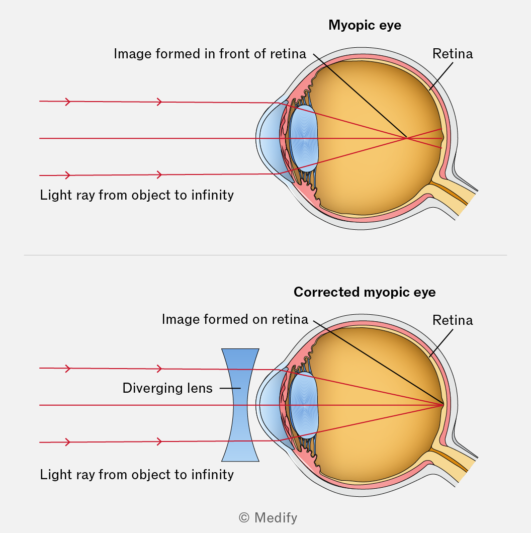
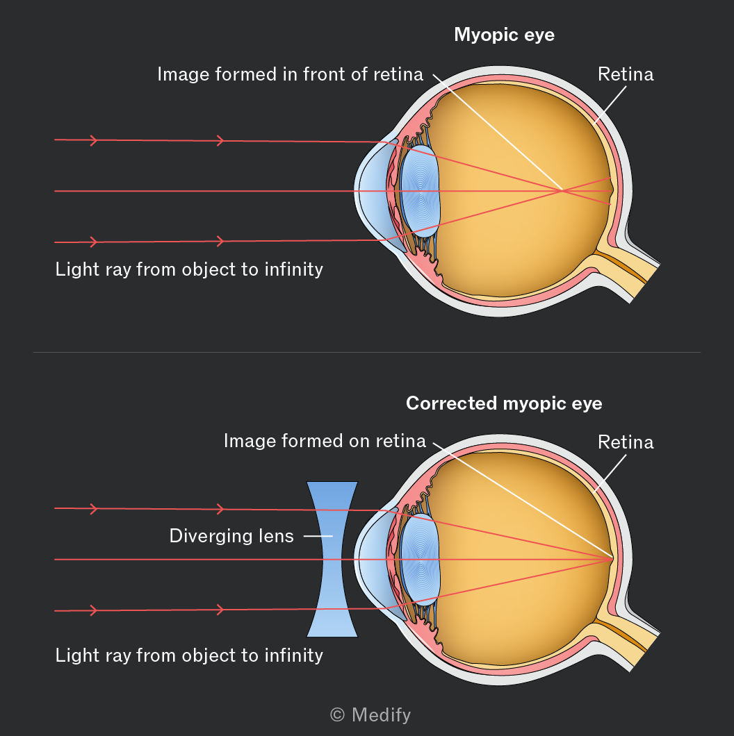
To correct for short-sightedness, a diverging lens is used that has a principal focus at the eye’s incorrect far point. This lens has a negative focal length, and the focal length of the lens needs to be the same distance as the faulty eye’s far point.
Therefore, an object at infinity, which was initially out of focus, is now in focus at the far point. The diverging lens spreads the light rays before they enter the eye, which shifts the image formation further back onto the retina.
Long-sightedness, also known as hypermetropia, describes people who can not focus on close objects. This occurs when their near point is further away than normal.
It is caused by the cornea and/or lens being too weak or the eye being too short. The focusing power of the eye is too weak; therefore, rather than the image being formed on the retina, it forms behind the retina.
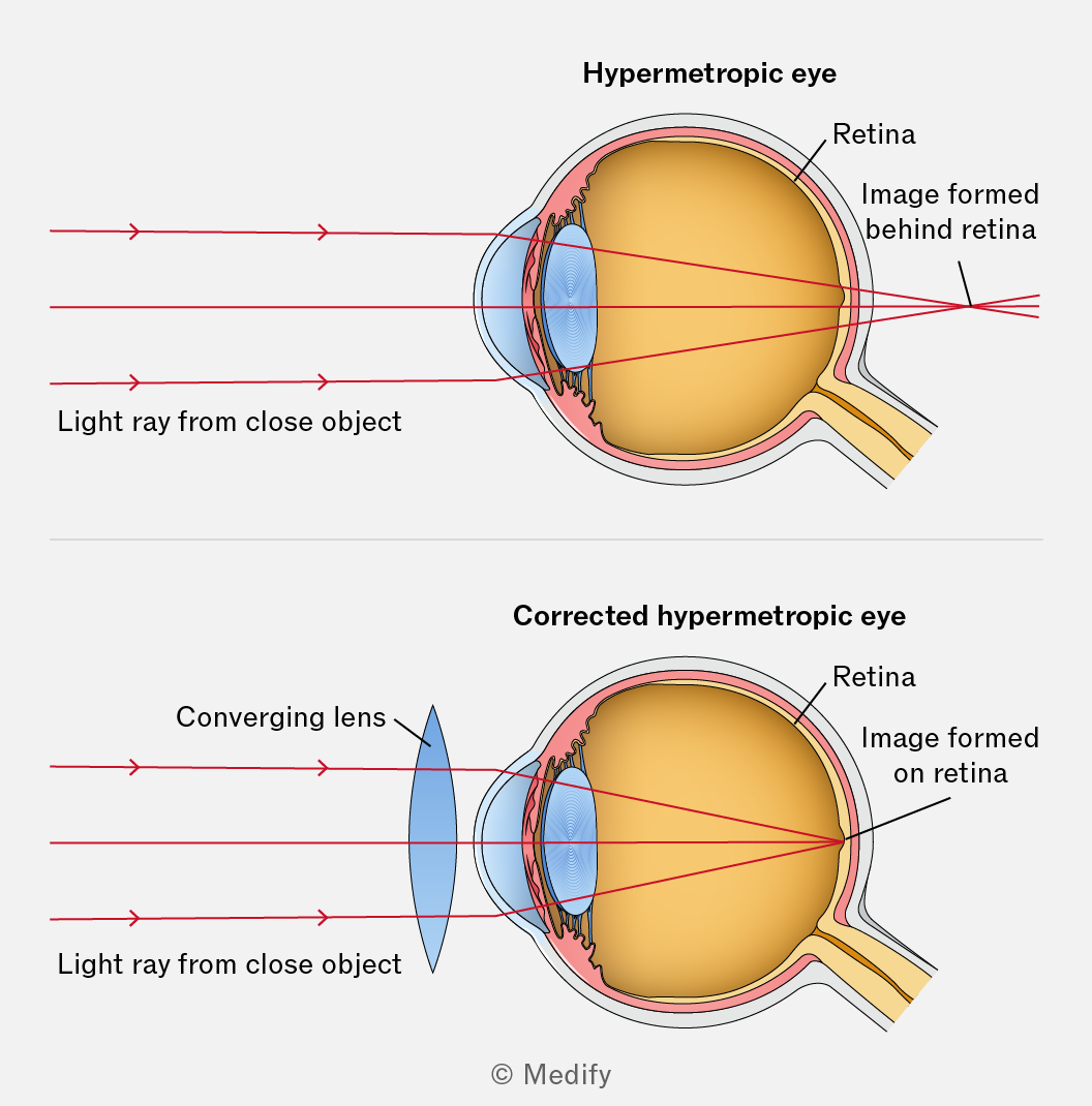
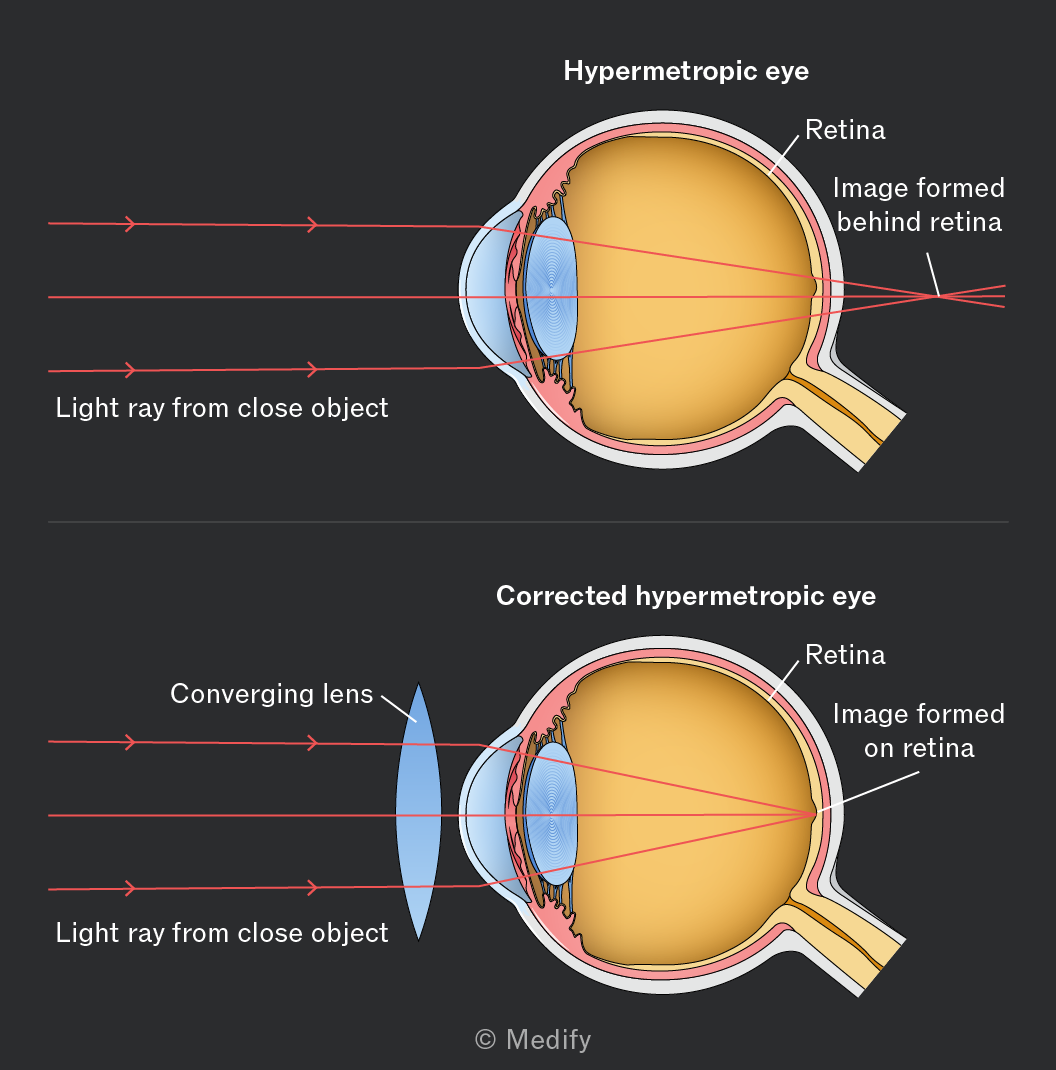
A converging lens must be used to correct for long-sightedness and to bring the image to a point further forward on the retina. This lens is required to produce images of objects away at the eye’s near point.
Therefore, close objects that were initially out of focus and are now in focus at the eye’s near point. A converging lens brings the light rays closer together before they enter the eye, which causes the formation of the image to move forward and onto the retina.
Question walkthrough
Finding lens power for short-sightedness
Uses 1/f=1/u+1/v, with the object at infinity and a negative image distance at the eye’s actual far point, to find the diverging lens power needed to correct short-sightedness.
Question walkthrough
Finding lens power for long-sightedness
Uses 1/f=1/u+1/v, with the object at the normal near point and a negative image distance at the eye’s actual (farther) near point, to find the converging lens power needed to correct long-sightedness.
Astigmatism is caused by an irregularly shaped cornea and/or lens, resulting in different focal lengths for different planes.
A normal eye is shaped like a round ball, but with astigmatism, it is more like a rugby ball or an egg, distorting how light is focused onto the retina. For example, light rays in the horizontal plane may be in focus, but vertically oriented light rays may not be.
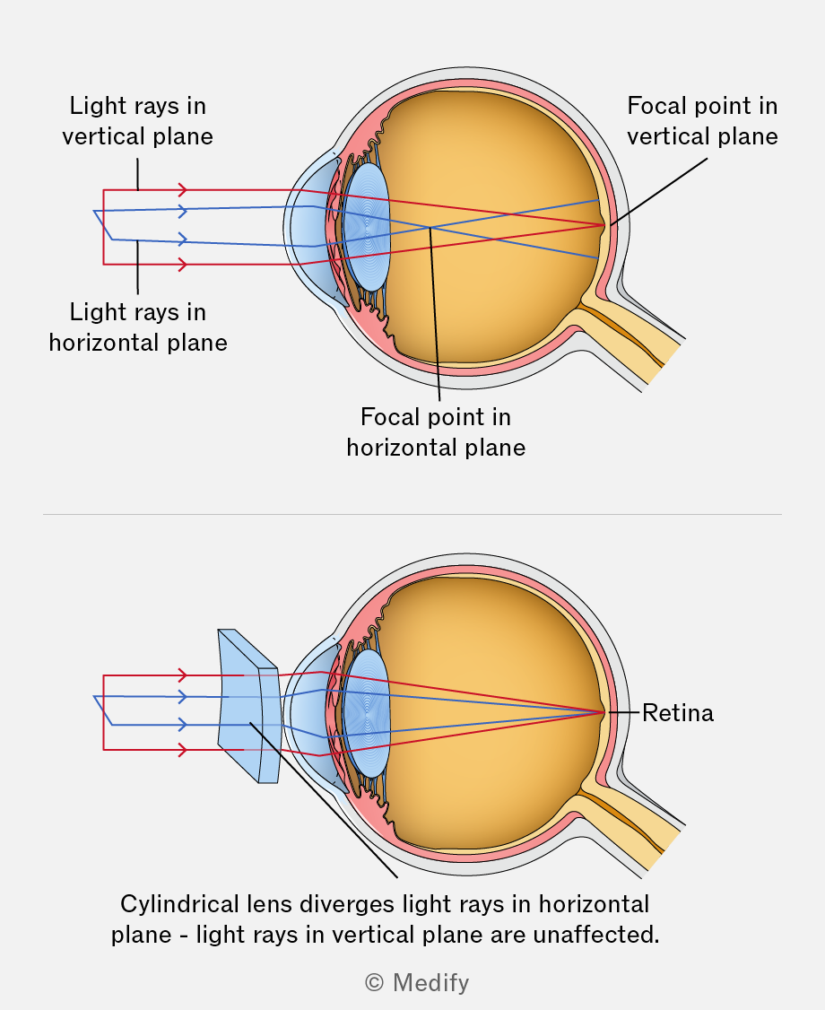
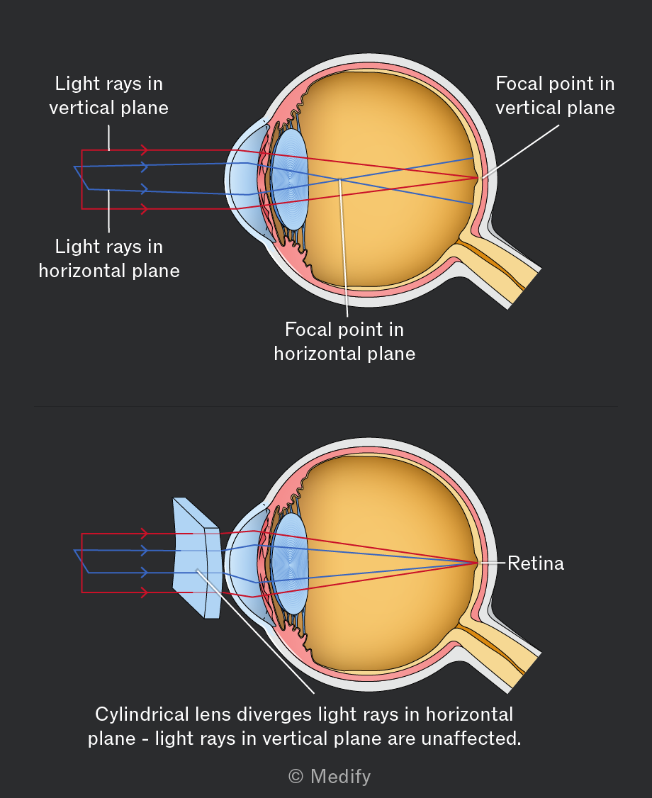
Astigmatism is corrected using a cylindrical lens. A cylindrical lens changes the refractive power in one plane only, while having little or no effect in the perpendicular plane. It is oriented so that it compensates for the eye’s unequal focusing power, bringing light rays from both planes to the same focus on the retina.
The prescription from an optician for a cylindrical lens describes the power needed to correct for short-sightedness or long-sightedness.
It also describes the power required to correct for astigmatism and the angle to the horizontal of the plane that does not require correction. An example prescription for an individual with astigmatism is shown in the table below.
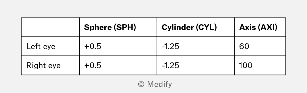
- Sphere: the spherical component of the prescription. It is the amount of correction, in diopters, required to correct for the short-sightedness or the long-sightedness.
- Cylinder: the cylindrical component of the prescription, used to correct astigmatism. This value, measured in dioptres, can be positive or negative. If no astigmatism is present, this value is usually 0.00D or left blank.
- Axis: The axis specifies the orientation of the cylindrical lens. It is measured in degrees (from 1 to 180) using a protractor-like semicircle and specifies the lens’s angle within the frame.