
Series and parallel circuits (4.3.1)
On this page
Kirchhoff’s second law states that the sum of the electromotive force (EMF) is equal to the sum of the potential difference (p.d.) in a loop of a circuit.
Alternatively, the sum of the EMF and the p.d. in a loop of a circuit is equal to zero:
- EMF is energy per unit charge (voltage) transferred from chemical to electrical energy. It is produced by an electrochemical cell or a changing magnetic field.
- p.d. across a component is energy per unit charge (voltage) dissipated across the component.
So, this law is a consequence of the conservation of energy.
In any circuit loop, potential rises across batteries or cells by their EMF and drops across components by their resistance multiplied by the current flowing through them.
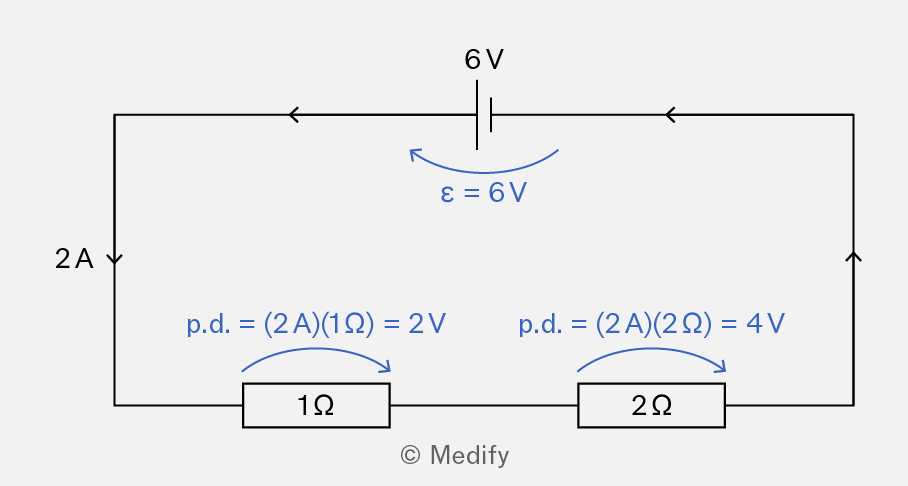
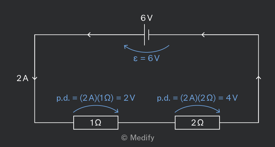
The sum of the EMF is equal to the sum of the p.d. in any loop of a circuit.
If the direction of the current is negative in any part of a loop, then the direction of the p.d. is negative.
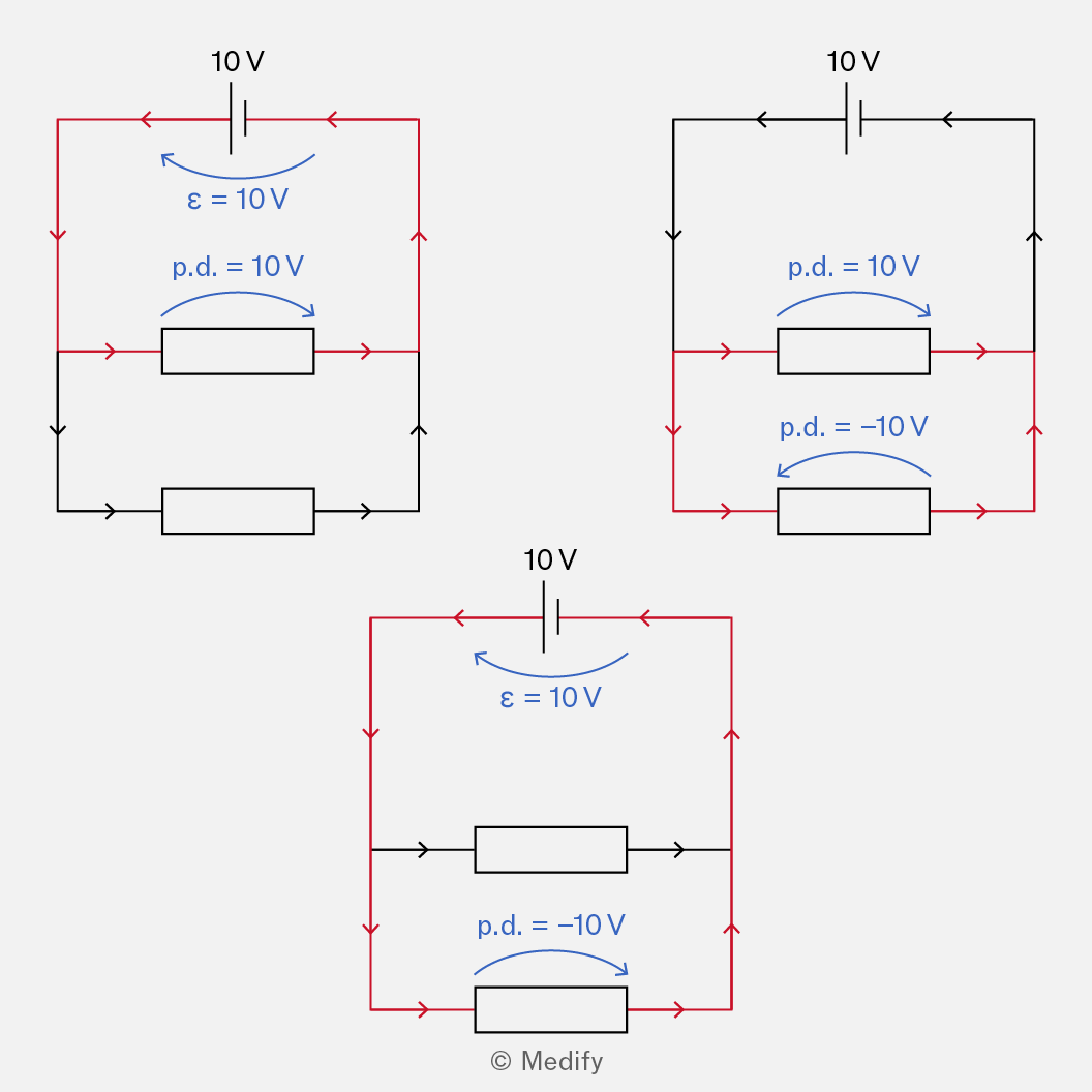
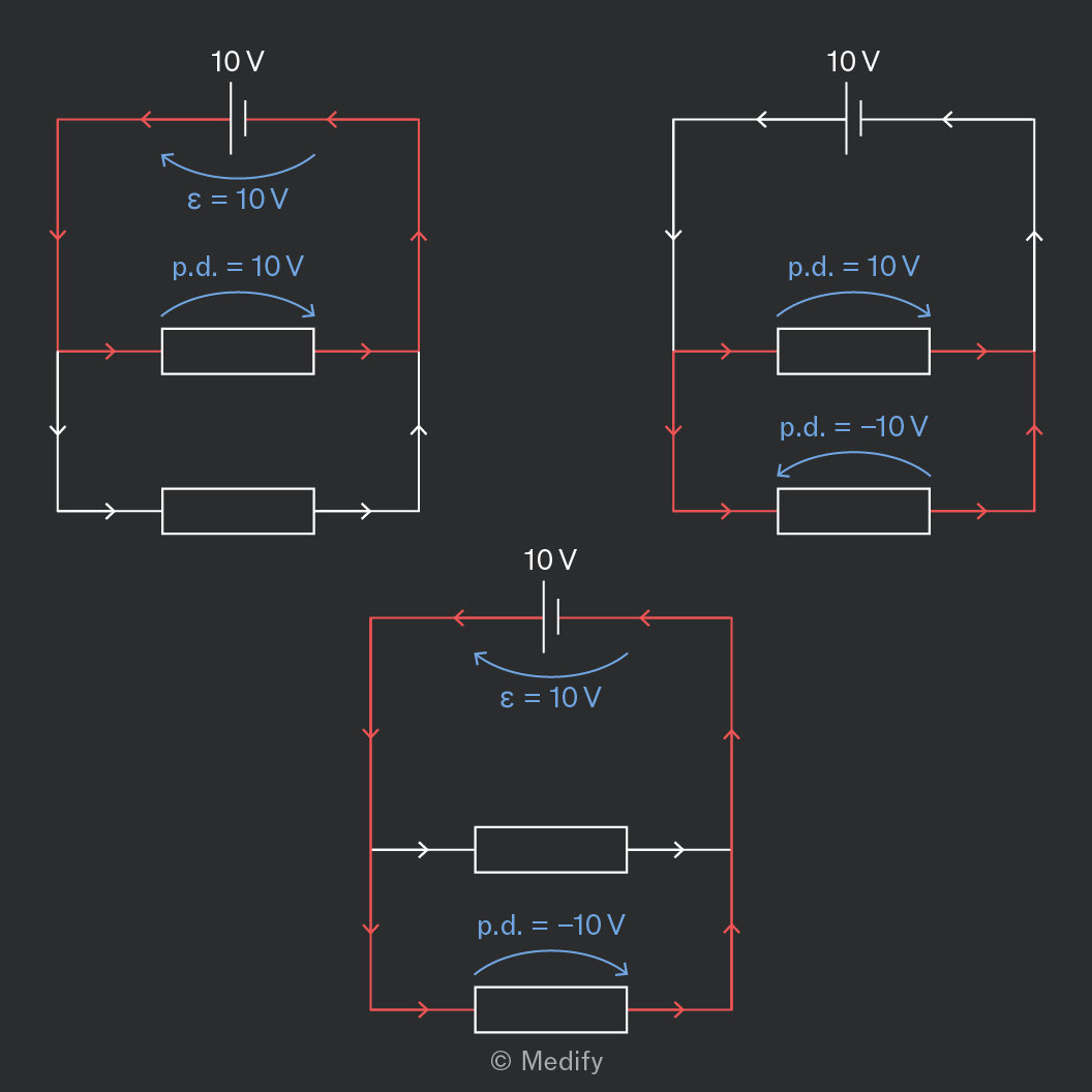
Only the red parts of the circuit are the loop being analysed in the examples above. Black sections are part of the real circuit but aren’t used in that loop’s equation.
Curved arrows show the direction you’re tracing the loop, not the actual current direction.
Trace with the current and the p.d. is positive; trace against it and the p.d. is negative, even though the resistor’s real p.d. hasn’t changed.
Question walkthrough
Using Kirchhoff's Second Law to Find Voltage
Apply Kirchhoff's second law to a series circuit with a thermistor and filament lamp to find a missing voltmeter reading from the cell EMF and one known p.d.
Question walkthrough
Finding Potential Difference Between Two Points
Calculate the potential difference between two points in a circuit by finding the p.d. across each branch with Ohm's law and taking their difference.
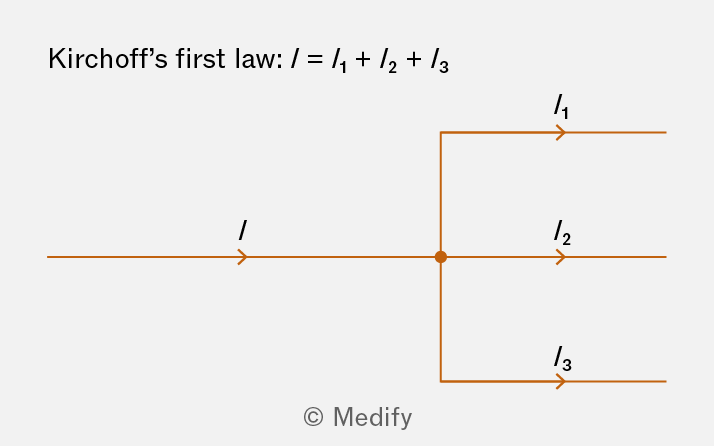
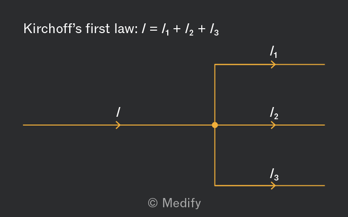
Kirchhoff’s first law states that the sum of the current flowing into a junction is equal to the current flowing out of a junction.
Question walkthrough
Applying Kirchhoff's Current Law at Junctions
Determine three unknown branch currents by applying Kirchhoff's current law at successive junctions in a multi-branch circuit.
Question walkthrough
Solving for Unknown Ammeter and Voltmeter Readings
Find ammeter and voltmeter readings in a series-parallel circuit using Ohm's law and current splitting across parallel resistors, with an alternative potential-divider method.
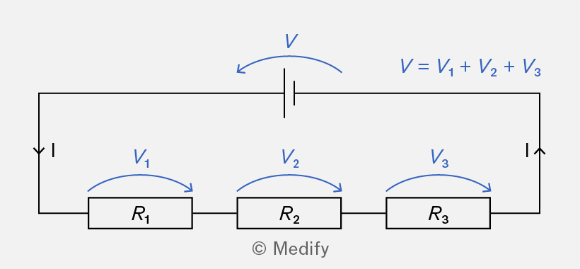
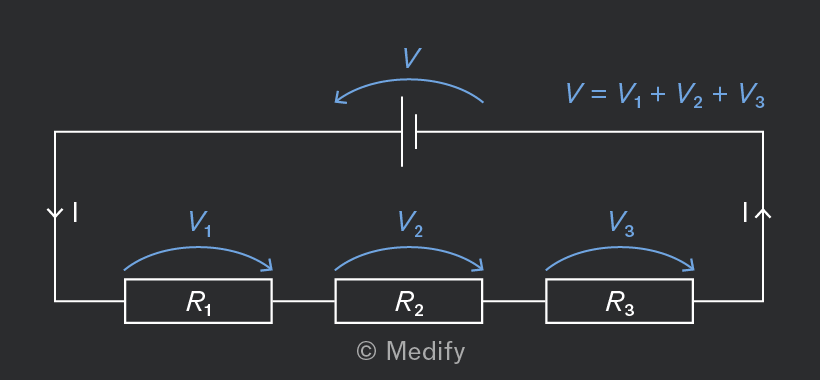
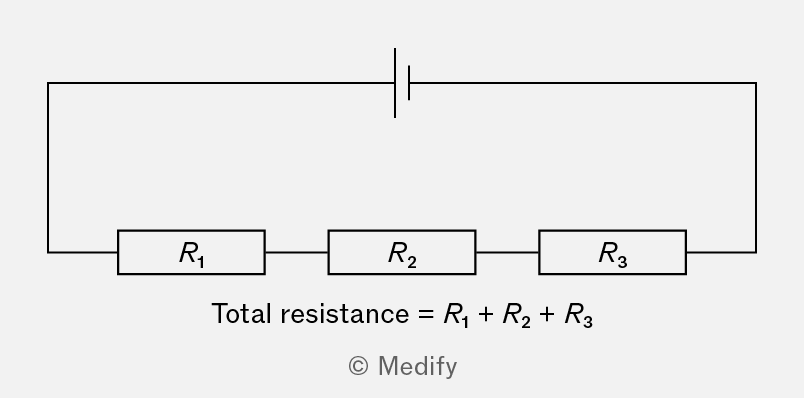
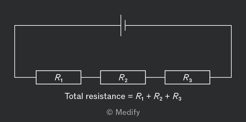
In a series circuit:
- the current through each resistor is the same.
- the sum of the voltages across the resistors is equal to the total voltage.
The total resistance of two or more resistors in series is given by:
Question walkthrough
Calculating Current in a Series Circuit
Find the current in a series circuit by summing three resistances to get the total resistance, then applying Ohm's law.
Question walkthrough
Deriving the Series Resistors Formula
Derive the total resistance formula for three resistors in series from Kirchhoff's voltage law and Ohm's law, showing each algebraic step.
In a parallel circuit:
- the voltage across each resistor is the same,
- the sum of the currents through the resistors is equal to the total current.
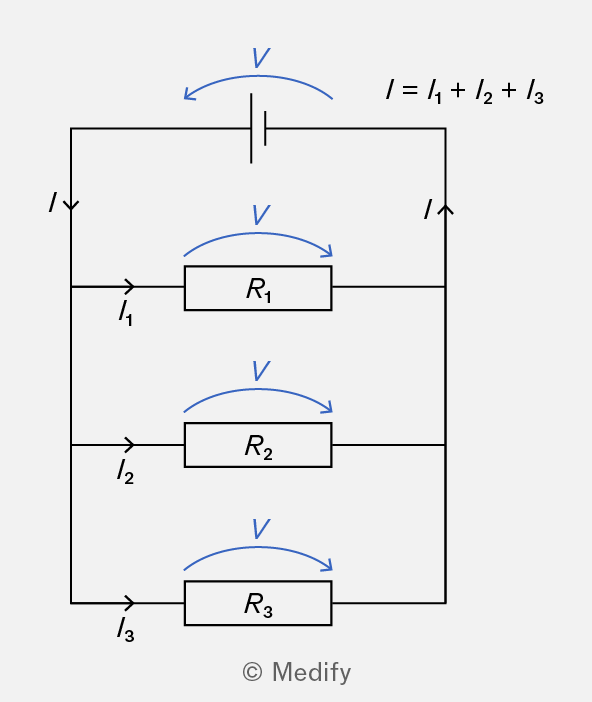
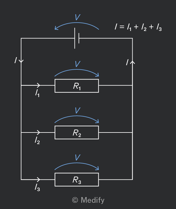
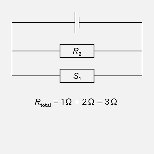
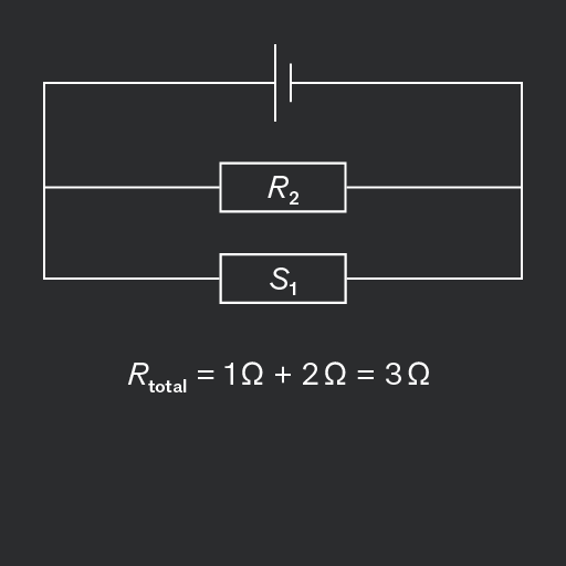
The total resistance of two or more resistors in parallel is given by:
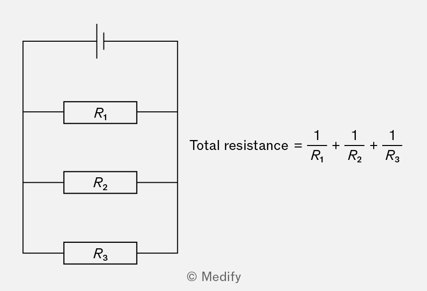
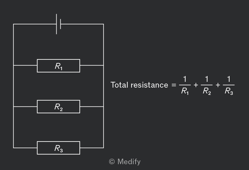
It is important to recall the correct formula for a circuit in parallel.
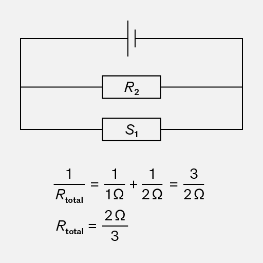
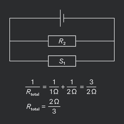
Question walkthrough
Find total resistance in a circuit
By analysing and interpreting a circuit diagram, determine the total resistance in a circuit and the EMF of the power source.
Question walkthrough
Deriving the Parallel Resistors Formula
Derive the total resistance formula for three parallel resistors from Kirchhoff's current law and Ohm's law, showing each algebraic step.
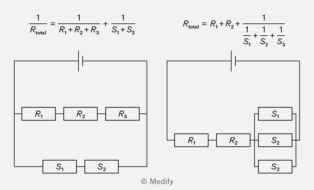
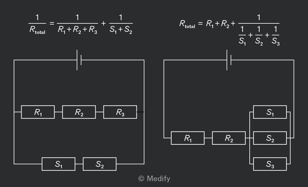
Some circuits contain both series (denoted in the diagram as ) and parallel combinations. In such cases, the equations for series and parallel resistors can be combined.
Question walkthrough
Finding LED Resistance in a Mixed Circuit
Calculate an LED's resistance in a circuit combining series and parallel resistors, using Ohm's law and the reciprocal rule for parallel combinations.
Question walkthrough
Combining Three Parallel Resistor Branches
Practise finding total resistance for a network with three parallel branches, including a branch made of two series resistors, using the reciprocal formula for parallel combinations.
Question walkthrough
Finding Cell Current Using a Filament Graph
Uses a non-linear voltage-current graph for a filament lamp to find branch currents in a series-parallel circuit and the total current in the cell.
When analysing circuits with multiple cells, use Kirchhoff’s second law to form equations relating EMF, current and resistance.
- Potential rises by across cells, where is the resistance of the cell.
- Potential drops by across components (including internal resistors) where is the current flowing through the component and is its resistance.
For two cells in series, the total EMF is equal to the sum of the EMF of each source.
If two cells of EMF, and point in the same direction, then the total EMF will be:
If two cells of EMF, and where point in opposite directions, then the total EMF will be:
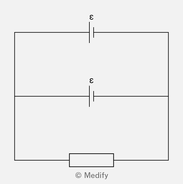
Connecting two cells of different EMF with no internal resistance in parallel will cause a dangerously high current to flow through the connecting wires, resulting in a short circuit. This occurs because there is a nonzero EMF (equal to the difference in EMF of the two cells) across a wire which has a very low resistance:
Therefore, large and small lead to a small For two cells of identical EMF in parallel, the total EMF remains
Question walkthrough
Finding Current in Opposing Cells
Finds the magnitude and direction of current in a series circuit containing two cells connected in opposing directions.
Question walkthrough
Finding Thermistor Resistance from Ammeter Reading
Uses circuit symmetry with Kirchhoff's laws to find the current through a thermistor and calculate its resistance from an ammeter reading.
Question walkthrough
Solving Branch Currents with Kirchhoff's Laws
Applies Kirchhoff's first and second laws to a two-loop circuit to solve simultaneously for three unknown branch currents.
Question walkthrough
Resistance Effect on Meter Readings
Explains why increasing a variable resistor's resistance in a two-cell circuit has no effect on the voltmeter or ammeter readings across the fixed resistor.